第7章化学結合と分子の形
7.6 Molecular Structure and Polarity7.6 分子構造と極性
Learning Objectives学習目標
By the end of this section, you will be able to:
この節を学ぶと、次のことができるようになる。
- Predict the structures of small molecules using valence shell electron pair repulsion (VSEPR) theory原子価殻電子対反発(VSEPR)理論を使い、小さな分子の構造を予測する。
- Explain the concepts of polar covalent bonds and molecular polarity極性共有結合と分子の極性の概念を説明する。
- Assess the polarity of a molecule based on its bonding and structure結合と構造をもとに、分子の極性を判断する。
Thus far, we have used two-dimensional Lewis structures to represent molecules. However, molecular structure is actually three-dimensional, and it is important to be able to describe molecular bonds in terms of their distances, angles, and relative arrangements in space (Figure 7.14). A bond angle is the angle between any two bonds that include a common atom, usually measured in degrees. A bond distance (or bond length) is the distance between the nuclei of two bonded atoms along the straight line joining the nuclei. Bond distances are measured in Ångstroms (1 Å = 10–10 m) or picometers (1 pm = 10–12 m, 100 pm = 1 Å).
英語のヒント
これまでは、二次元のルイス構造を用いて分子を表してきた。しかし分子構造は実際には三次元であり、分子の結合を、距離、角度、空間内での相対的配置によって説明できることが重要である(図7.14)。結合角とは、1つの原子を共有する2本の結合の間の角度で、通常は度で測る。結合距離(結合長)とは、結合した2原子の原子核を結ぶ直線に沿って測った、原子核間の距離である。結合距離には、オングストローム(1 Å = 10–10 m)またはピコメートル(1 pm = 10–12 m、100 pm = 1 Å)を用いる。
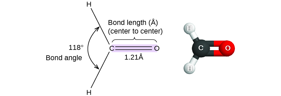
Figure 7.14図 7.14
Bond distances (lengths) and angles are shown for the formaldehyde molecule, H2CO.
ホルムアルデヒドH2COの結合距離(結合長)と結合角。
VSEPR TheoryVSEPR理論
Valence shell electron-pair repulsion theory (VSEPR theory) enables us to predict the molecular structure, including approximate bond angles around a central atom, of a molecule from an examination of the number of bonds and lone electron pairs in its Lewis structure. The VSEPR model assumes that electron pairs in the valence shell of a central atom will adopt an arrangement that minimizes repulsions between these electron pairs by maximizing the distance between them. The electrons in the valence shell of a central atom form either bonding pairs of electrons, located primarily between bonded atoms, or lone pairs. The electrostatic repulsion of these electrons is reduced when the various regions of high electron density assume positions as far from each other as possible.
英語のヒント
原子価殻電子対反発理論(VSEPR理論)では、ルイス構造の結合と非共有電子対の数を調べることで、中心原子の周りのおおよその結合角を含め、分子構造を予測できる。VSEPRモデルでは、中心原子の価電子殻にある電子対は、互いの距離を最大にして反発を最小にする配置をとると仮定する。中心原子の価電子殻の電子は、主として結合した原子間にある結合電子対か、非共有電子対をつくる。電子密度の高い領域どうしができるだけ離れた位置をとると、これらの電子間の静電反発が小さくなる。
VSEPR theory predicts the arrangement of electron pairs around each central atom and, usually, the correct arrangement of atoms in a molecule. We should understand, however, that the theory only considers electron-pair repulsions. Other interactions, such as nuclear-nuclear repulsions and nuclear-electron attractions, are also involved in the final arrangement that atoms adopt in a particular molecular structure.
VSEPR理論は、各中心原子の周りの電子対の配置を予測し、通常は、分子内の原子の正しい配置も予測する。しかし、この理論が考慮するのは電子対間の反発だけであることを理解しておこう。特定の分子構造で原子が最終的にとる配置には、原子核間の反発や原子核–電子間の引力など、他の相互作用も関わる。
As a simple example of VSEPR theory, let us predict the structure of a gaseous BeF2 molecule. The Lewis structure of BeF2 (Figure 7.15) shows only two electron pairs around the central beryllium atom. With two bonds and no lone pairs of electrons on the central atom, the bonds are as far apart as possible, and the electrostatic repulsion between these regions of high electron density is reduced to a minimum when they are on opposite sides of the central atom. The bond angle is 180° (Figure 7.15).

Figure 7.15図 7.15
The BeF2 molecule adopts a linear structure in which the two bonds are as far apart as possible, on opposite sides of the Be atom.
BeF2分子は、2本の結合がBe原子の反対側に位置して最大限離れる、直線形の構造をとる。
Figure 7.16 illustrates this and other electron-pair geometries that minimize the repulsions among regions of high electron density (bonds and/or lone pairs). Two regions of electron density around a central atom in a molecule form a linear geometry; three regions form a trigonal planar geometry; four regions form a tetrahedral geometry; five regions form a trigonal bipyramidal geometry; and six regions form an octahedral geometry.
英語のヒント
図7.16は、この配置と、電子密度の高い領域(結合や非共有電子対)間の反発を最小にする他の電子対配置を示す。分子の中心原子の周りに電子密度の高い領域が2つあると直線形、3つなら平面三角形、4つなら正四面体形、5つなら三方両錐形、6つなら正八面体形になる。
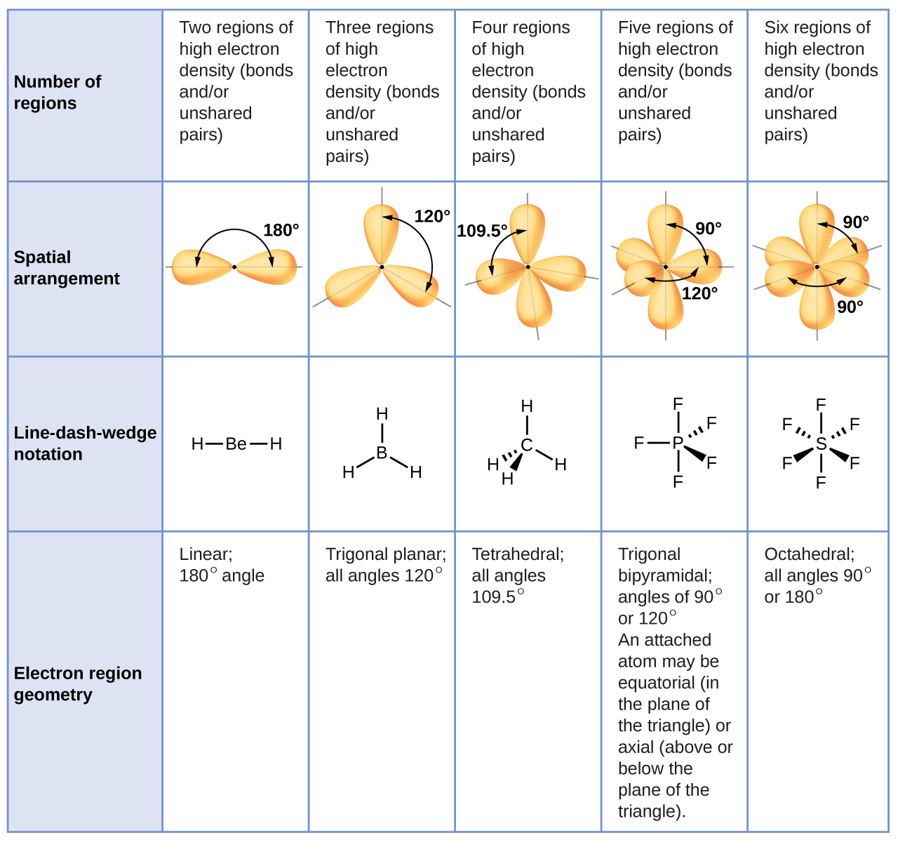
Figure 7.16図 7.16
The basic electron-pair geometries predicted by VSEPR theory maximize the space around any region of electron density (bonds or lone pairs).
VSEPR理論が予測する基本的な電子対配置は、電子密度の高い各領域(結合または非共有電子対)の周囲の空間を最大限に確保する。
Electron-pair Geometry versus Molecular Structure電子対の配置と分子構造
It is important to note that electron-pair geometry around a central atom is not the same thing as its molecular structure. The electron-pair geometries shown in Figure 7.16 describe all regions where electrons are located, bonds as well as lone pairs. Molecular structure describes the location of the atoms, not the electrons.
中心原子の周りの電子対配置と、分子構造は同じものではない。この点に注意することが重要である。図7.16の電子対配置は、結合と非共有電子対の両方を含め、電子が存在するすべての領域を表す。分子構造が表すのは、電子ではなく原子の位置である。
We differentiate between these two situations by naming the geometry that includes all electron pairs the electron-pair geometry. The structure that includes only the placement of the atoms in the molecule is called the molecular structure. The electron-pair geometries will be the same as the molecular structures when there are no lone electron pairs around the central atom, but they will be different when there are lone pairs present on the central atom.
英語のヒント
この2つを区別するため、すべての電子対を含めた配置を電子対配置と呼ぶ。分子内の原子の配置だけを含む構造は、分子構造と呼ぶ。中心原子の周りに非共有電子対がなければ、電子対配置と分子構造は同じになる。中心原子に非共有電子対があれば、両者は異なる。
For example, the methane molecule, CH4, which is the major component of natural gas, has four bonding pairs of electrons around the central carbon atom; the electron-pair geometry is tetrahedral, as is the molecular structure (Figure 7.17). On the other hand, the ammonia molecule, NH3, also has four electron pairs associated with the nitrogen atom, and thus has a tetrahedral electron-pair geometry. One of these regions, however, is a lone pair, which is not included in the molecular structure, and this lone pair influences the shape of the molecule (Figure 7.18).
英語のヒント
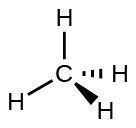
Figure 7.17図 7.17
The molecular structure of the methane molecule, CH4, is shown with a tetrahedral arrangement of the hydrogen atoms. VSEPR structures like this one are often drawn using the wedge and dash notation, in which solid lines represent bonds in the plane of the page, solid wedges represent bonds coming up out of the plane, and dashed lines represent bonds going down into the plane.
英語のヒント
メタンCH4の分子構造では、水素原子が正四面体状に配置される。このようなVSEPR構造は、くさびと破線で表すことが多い。実線は紙面内の結合、塗りつぶしたくさびは紙面から手前に出る結合、破線は紙面の奥へ向かう結合を表す。
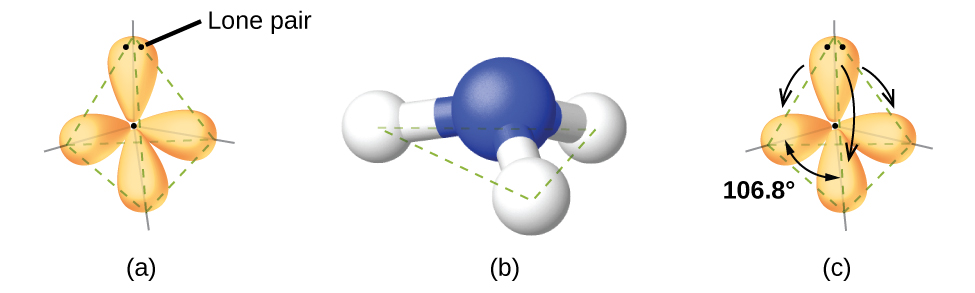
Figure 7.18図 7.18
(a) The electron-pair geometry for the ammonia molecule is tetrahedral with one lone pair and three single bonds. (b) The trigonal pyramidal molecular structure is determined from the electron-pair geometry. (c) The actual bond angles deviate slightly from the idealized angles because the lone pair takes up a larger region of space than do the single bonds, causing the HNH angle to be slightly smaller than 109.5°.
英語のヒント
(a) アンモニア分子の電子対配置は、非共有電子対1組と単結合3本による正四面体形である。(b) 電子対配置から、三角錐形の分子構造が決まる。(c) 非共有電子対は単結合よりも広い空間を占めるため、実際の結合角は理想的な角度から少しずれる。その結果、HNH角は109.5°よりわずかに小さくなる。
As seen in Figure 7.18, small distortions from the ideal angles in Figure 7.16 can result from differences in repulsion between various regions of electron density. VSEPR theory predicts these distortions by establishing an order of repulsions and an order of the amount of space occupied by different kinds of electron pairs. The order of electron-pair repulsions from greatest to least repulsion is:
英語のヒント
This order of repulsions determines the amount of space occupied by different regions of electrons. A lone pair of electrons occupies a larger region of space than the electrons in a triple bond; in turn, electrons in a triple bond occupy more space than those in a double bond, and so on. The order of sizes from largest to smallest is:
英語のヒント
この反発の順序が、それぞれの電子領域の占める空間の大きさを決める。非共有電子対は三重結合の電子より広い空間を占め、次に、三重結合の電子は二重結合の電子より広い空間を占める、といった順になる。大きいものから小さいものへの順序は次のとおりである。
Consider formaldehyde, H2CO, which is used as a preservative for biological and anatomical specimens (Figure 7.14). This molecule has regions of high electron density that consist of two single bonds and one double bond. The basic geometry is trigonal planar with 120° bond angles, but we see that the double bond causes slightly larger angles (121°), and the angle between the single bonds is slightly smaller (118°).
英語のヒント
生物標本や解剖標本の保存剤として使われるホルムアルデヒドH2COを考えよう(図7.14)。この分子の電子密度の高い領域は、単結合2本と二重結合1本からなる。基本的な配置は結合角120°の平面三角形だが、二重結合のため、その隣の角度は少し大きく121°となり、単結合どうしの角度は少し小さい118°となる。
In the ammonia molecule, the three hydrogen atoms attached to the central nitrogen are not arranged in a flat, trigonal planar molecular structure, but rather in a three-dimensional trigonal pyramid (Figure 7.18) with the nitrogen atom at the apex and the three hydrogen atoms forming the base. The ideal bond angles in a trigonal pyramid are based on the tetrahedral electron pair geometry. Again, there are slight deviations from the ideal because lone pairs occupy larger regions of space than do bonding electrons. The H–N–H bond angles in NH3 are slightly smaller than the 109.5° angle in a regular tetrahedron (Figure 7.16) because the lone pair-bonding pair repulsion is greater than the bonding pair-bonding pair repulsion (Figure 7.18). Figure 7.19 illustrates the ideal molecular structures, which are predicted based on the electron-pair geometries for various combinations of lone pairs and bonding pairs.
英語のヒント
アンモニアでは、中心の窒素に結合した3個の水素原子は、平らな平面三角形状には並ばない。窒素が頂点、3個の水素が底面をつくる、立体的な三角錐形に配置される(図7.18)。三角錐の理想的な結合角は、正四面体形の電子対配置をもとにする。この場合も、非共有電子対が結合電子より広い空間を占めるため、理想的な値から少しずれる。NH3のH–N–H結合角は、正四面体の109.5°(図7.16)よりわずかに小さい。非共有電子対–結合電子対間の反発のほうが、結合電子対どうしの反発より強いためである(図7.18)。図7.19には、非共有電子対と結合電子対のさまざまな組み合わせについて、電子対配置をもとに予測した理想的な分子構造を示す。
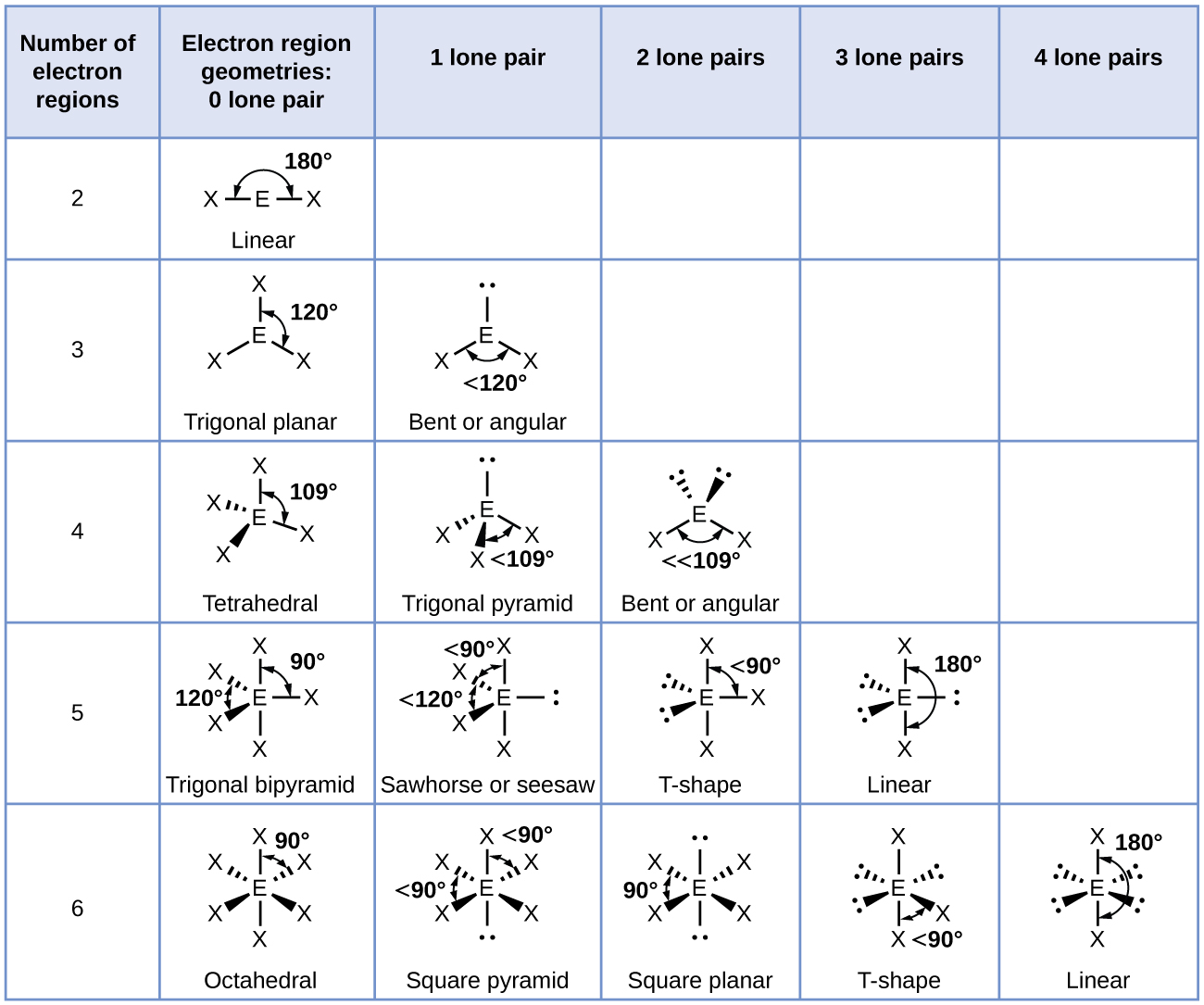
Figure 7.19図 7.19
The molecular structures are identical to the electron-pair geometries when there are no lone pairs present (first column). For a particular number of electron pairs (row), the molecular structures for one or more lone pairs are determined based on modifications of the corresponding electron-pair geometry.
非共有電子対がない場合(最初の列)、分子構造は電子対配置と一致する。各行の電子対数について、非共有電子対が1組以上ある場合の分子構造は、対応する電子対配置に変更を加えて決める。
According to VSEPR theory, the terminal atom locations (Xs in Figure 7.19) are equivalent within the linear, trigonal planar, and tetrahedral electron-pair geometries (the first three rows of the table). It does not matter which X is replaced with a lone pair because the molecules can be rotated to convert positions. For trigonal bipyramidal electron-pair geometries, however, there are two distinct X positions, as shown in Figure 7.20: an axial position (if we hold a model of a trigonal bipyramid by the two axial positions, we have an axis around which we can rotate the model) and an equatorial position (three positions form an equator around the middle of the molecule). As shown in Figure 7.19, the axial position is surrounded by bond angles of 90°, whereas the equatorial position has more space available because of the 120° bond angles. In a trigonal bipyramidal electron-pair geometry, lone pairs always occupy equatorial positions because these more spacious positions can more easily accommodate the larger lone pairs.
英語のヒント
VSEPR理論によれば、直線形、平面三角形、正四面体形の電子対配置(表の最初の3行)では、末端原子の位置(図7.19のX)は互いに等価である。分子を回転させれば位置を入れ替えられるので、どのXを非共有電子対に置き換えても違いはない。しかし三方両錐形では、図7.20のようにXの位置に2種類ある。1つは軸位で、三方両錐の模型の2つの軸位を持つと、その軸の周りに模型を回せる。もう1つは赤道位で、分子中央の周りの3つの位置が赤道をつくる。図7.19に示すように、軸位の周りには90°の結合角があるのに対し、赤道位は結合角が120°で、より広い空間を使える。三方両錐形の電子対配置では、非共有電子対は常に赤道位を占める。広い空間を必要とする非共有電子対を、より余裕のある赤道位のほうが収容しやすいためである。
Theoretically, we can come up with three possible arrangements for the three bonds and two lone pairs for the ClF3 molecule (Figure 7.20). The stable structure is the one that puts the lone pairs in equatorial locations, giving a T-shaped molecular structure.
英語のヒント
ClF3分子の3本の結合と2組の非共有電子対には、理論上3通りの配置が考えられる(図7.20)。安定なのは、非共有電子対を赤道位に配置するもので、その分子構造はT字形となる。
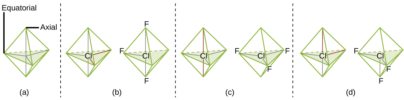


Figure 7.20図 7.20
(a) In a trigonal bipyramid, the two axial positions are located directly across from one another, whereas the three equatorial positions are located in a triangular arrangement. (b–d) The two lone pairs (red lines) in ClF3 have several possible arrangements, but the T-shaped molecular structure (b) is the one actually observed, consistent with the larger lone pairs both occupying equatorial positions.
(a) 三方両錐では、2つの軸位が互いに正反対に位置し、3つの赤道位が三角形に配置される。(b)〜(d) ClF3の2組の非共有電子対(赤い線)にはいくつかの配置が考えられるが、実際に観測されるのは(b)のT字形である。これは、空間を広く占める非共有電子対が両方とも赤道位にあることと整合する。
When a central atom has two lone electron pairs and four bonding regions, we have an octahedral electron-pair geometry. The two lone pairs are on opposite sides of the octahedron (180° apart), giving a square planar molecular structure that minimizes lone pair-lone pair repulsions (Figure 7.19).
中心原子が非共有電子対を2組、結合領域を4つもつ場合、電子対配置は正八面体形になる。2組の非共有電子対は八面体の反対側(180°離れた位置)にあり、非共有電子対どうしの反発を最小にする正方形の分子構造となる(図7.19)。