第19章電気回路Electrical Circuits原書 p.623–668
19.2 Series Circuits19.2 直列回路
SECTION LEARNING OBJECTIVES By the end of this section, you will be able to do the following:
この節の学習目標 この節を終えると、次のことができるようになる。
• Interpret circuit diagrams and diagram basic circuit elements• Calculate equivalent resistance of resistors in series and apply Ohm’s law to resistors in series and apply Ohm’s law to resistors in series
・回路図を読み、基本的な回路の素子を図に描く・直列につないだ抵抗の合成抵抗を計算し、直列につないだ抵抗にオームの法則を当てはめる
Section Key Termsこの節の重要語
circuit diagramelectric circuitequivalent resistancein seriesresistorsteady state
回路図電気回路合成抵抗直列に抵抗器定常状態
Electric Circuits and Resistors電気回路と抵抗器
Now that we understand the concept of electric current, let’s see what we can do with it. As you are no doubt aware, the modern lifestyle relies heavily on electrical devices. These devices contain ingenious electric circuits, which are complete, closed pathways through which electric current flows. Returning to our water analogy, an electric circuit is to electric charge like a network of pipes is to water: The electric circuit guides electric charge from one point to the next, running the charge through various devices along the way to extract work or information.
電流の考えが分かったので、それで何ができるかを見よう。よく知ってのとおり、現代の暮らしは電気の装置に大きく頼っている。これらの装置には巧みな電気回路が入っている。電気回路とは、電流が流れる、完全に閉じた通り道である。水の類比に戻れば、電気回路が電荷に対して持つ関係は、管の網目が水に対して持つ関係と同じである。電気回路は電荷をある点から次の点へ導き、途中でいろいろな装置に電荷を通して仕事や情報を取り出す。
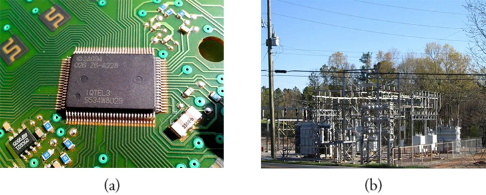
Electric circuits are made from many materials and cover a huge range of sizes, as shown in Figure 19.8. Computers and cell phones contain electric circuits whose features can be as small as roughly a billionth of a meter (a nanometer, or ). The pathways that guide the current in these devices are made by ultraprecise chemical treatments of silicon or other semiconductors. Large power systems, on the other hand, contain electric circuits whose features are on the scale of meters. These systems carry such large electric currents that their physical dimensions must be relatively large.
図19.8に示すように、電気回路は多くの材料で作られ、大きさの幅もきわめて広い。コンピューターや携帯電話には、細部の大きさがおよそ10億分の1メートル(ナノメートル、すなわち)ほどの電気回路が入っている。こうした装置で電流を導く通り道は、シリコンなどの半導体をきわめて精密に化学処理して作られる。一方、大きな電力の系統には、細部がメートルの尺度の電気回路が入っている。こうした系統はきわめて大きな電流を運ぶので、物理的な寸法もそれなりに大きくなければならない。
The pathways that form electric circuits are made from a conducting material, normally a metal in macroscopic circuits. For example, copper wires inside your school building form the electrical circuits that power lighting, projectors, screens, speakers, etc. To represent an electric circuit, we draw circuit diagrams. We use lines and symbols to represent the elements in the circuit. A simple electric circuit diagram is shown on the left side of Figure 19.9. On the right side is an analogous water circuit, which we discuss below.
電気回路をなす通り道は導体の材料で作られ、巨視的な回路ではふつう金属である。たとえば学校の建物の中の銅線が、照明・プロジェクター・スクリーン・スピーカーなどに電力を供給する電気回路をなしている。電気回路を表すために、私たちは回路図を描く。回路の素子を表すのに線と記号を使う。単純な電気回路の図を図19.9の左側に示す。右側は同じ働きをする水の回路で、下で論じる。
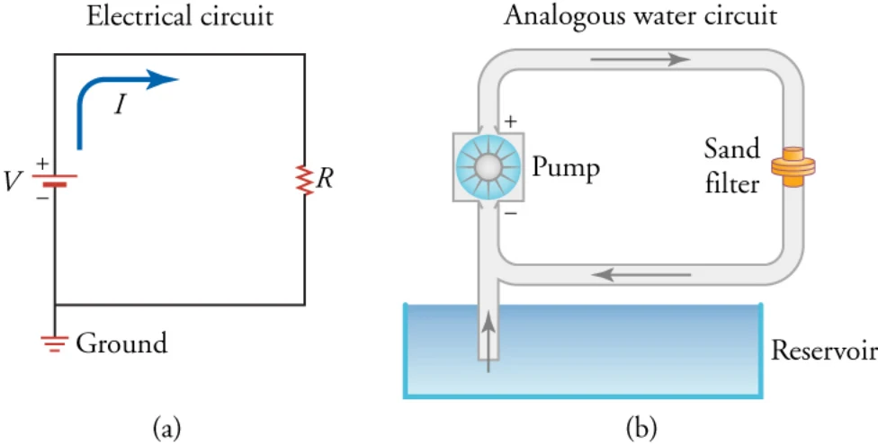
There are many different symbols that scientists and engineers use in circuit diagrams, but we will focus on four main symbols: the wire, the battery or voltage source, resistors, and the ground. The thin black lines in the electric circuit diagram represent the pathway that the electric charge must follow. These pathways are assumed to be perfect conductors, so electric charge can move along these pathways without losing any energy. In reality, the wires in circuits are not perfect, but they come close enough for our purposes.
科学者と技術者が回路図に使う記号はさまざまだが、ここでは主に四つの記号——導線、電池すなわち電圧源、抵抗器、接地——に集中する。電気回路図の細い黒い線は、電荷がたどらねばならない通り道を表す。この通り道は完全な導体とみなされるので、電荷はエネルギーを失わずにこの道を動ける。実際には回路の導線は完全ではないが、ここでの目的には十分近い。
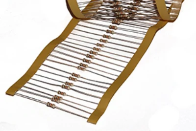
The zigzag element labeled R is a resistor, which is a circuit element that provides a known resistance. Macroscopic resistors are often color coded to indicate their resistance, as shown in Figure 19.10.
Rと書かれたジグザグの素子は抵抗器で、決まった抵抗を与える回路の素子である。巨視的な抵抗器は、図19.10に示すように、抵抗値を示す色で表示されていることが多い。
The red element in Figure 19.9 is a battery, with its positive and negative terminals indicated; the longer line represents the positive terminal of the battery, and the shorter line represents the negative terminal. Note that the battery icon is not always colored red; this is done in Figure 19.9 just to make it easy to identify.
図19.9の赤い素子は電池で、正と負の端子が示されている。長い線が電池の正の端子、短い線が負の端子を表す。電池の記号がいつも赤いわけではないことに注意しよう。図19.9で赤くしてあるのは、見分けやすくするためだけである。
Finally, the element labeled ground on the lower left of the circuit indicates that the circuit is connected to Earth, which is a large, essentially neutral object containing an infinite amount of charge. Among other things, the ground determines the potential of the negative terminal of the battery. Normally, the potential of the ground is defined to be zero: . This means that the entire lower wire in Figure 19.10 is at a voltage of zero volts.
最後に、回路の左下の「接地」と書かれた素子は、回路が地球につながれていることを示す。地球は大きく、実質的に中性で、無限の量の電荷を含む物体である。とりわけ接地は、電池の負の端子の電位を決める。ふつう接地の電位は0と定められる。。これは、図19.10の下の導線全体が0ボルトの電圧にあるという意味である。
The electric current in Figure 19.9 is indicted by the blue line labeled I. The arrow indicates the direction in which positive charge would flow in this circuit. Recall that, in metals, electrons are mobile charge carriers, so negative charges actually flow in the opposite direction around this circuit (i.e., counterclockwise). However, we draw the current to show the direction in which positive charge would move.
図19.9の電流は、Iと書かれた青い線で示されている。矢印は、この回路で正の電荷が流れるであろう向きを示す。金属では電子が動ける電荷の担い手なので、実際にはこの回路で負の電荷が逆向き(すなわち反時計回り)に流れることを思い出そう。しかし、正の電荷が動くであろう向きを示すために電流を描く。
On the right side of Figure 19.9 is an analogous water circuit. Water at a higher pressure leaves the top of the pump, which is like charges leaving the positive terminal of the battery. The water travels through the pipe, like the charges traveling through the wire. Next, the water goes through a sand filter, which heats up as the water squeezes through. This step is like the charges going through the resistor. When charges flow through a resistor, they do work to heat up the resistor. After flowing through the sand filter, the water has converted its potential energy into heat, so it is at a lower pressure. Likewise, the charges exiting the resistor have converted their potential energy into heat, so they are at a lower voltage. Recall that voltage is just potential energy per charge. Thus, water pressure is analogous to electric potential energy (i.e., voltage). Coming back to the water circuit again, we see that the water returns to the bottom of the pump, which is like the charge returning to the negative terminal of the battery. The water pump uses a source of energy to pump the water back up to a high pressure again, giving it the pressure required to go through the circuit once more. The water pump is like the battery, which uses chemical energy to increase the voltage of the charge up to the level of the positive terminal.
図19.9の右側は同じ働きをする水の回路である。より高い圧力の水がポンプの上から出ていく。これは電荷が電池の正の端子から出ていくのに似ている。水は管を通って進む。電荷が導線を通って進むのと同じである。次に水は砂のフィルターを通り、そこを絞り出されるときに熱くなる。この段階は電荷が抵抗器を通るのに似ている。電荷が抵抗器を通るとき、抵抗器を熱くする仕事をする。砂のフィルターを通り抜けたあと、水は位置エネルギーを熱へ変えてしまったので、より低い圧力にある。同じように、抵抗器から出てきた電荷は位置エネルギーを熱へ変えたので、より低い電圧にある。電圧とは電荷あたりの位置エネルギーにすぎないことを思い出そう。したがって水の圧力は電気的な位置エネルギー(すなわち電圧)にあたる。水の回路に戻ると、水はポンプの下へ戻る。これは電荷が電池の負の端子へ戻るのに似ている。水のポンプはエネルギー源を使って水をふたたび高い圧力まで汲み上げ、もう一度回路を巡るのに必要な圧力を与える。水のポンプは電池に似ている。電池は化学エネルギーを使って電荷の電圧を正の端子の高さまで上げる。
The potential energy per charge at the positive terminal of the battery is the voltage rating of the battery. This voltage is like water pressure in the upper pipe. Just like a higher pressure forces water to move toward a lower pressure, a higher voltage forces electric charge to flow toward a lower voltage. The pump takes water at low pressure and does work on it, ejecting water at a higher pressure. Likewise, a battery takes charge at a low voltage, does work on it, and ejects charge at a higher voltage.
電池の正の端子での電荷あたりの位置エネルギーが、電池の定格電圧である。この電圧は上の管の水の圧力に似ている。高い圧力が水を低い圧力のほうへ動かすのとちょうど同じように、高い電圧は電荷を低い電圧のほうへ流す。ポンプは低い圧力の水を受け取ってそれに仕事をし、より高い圧力の水を送り出す。同じように、電池は低い電圧の電荷を受け取り、それに仕事をして、より高い電圧の電荷を送り出す。
Note that the current in the water circuit of Figure 19.9 is the same throughout the circuit. In other words, if we measured the number of water molecules passing a cross-section of the pipe per unit time at any point in the circuit, we would get the same answer no matter where in the circuit we measured. The same is true of the electrical circuit in the same figure. The electric current is the same at all points in this circuit, including inside the battery and in the resistor. The electric current neither speeds up in the wires nor slows down in the resistor. This would create points where too much or too little charge would be bunched up. Thus, the current is the same at all points in the circuit shown in Figure 19.9.
図19.9の水の回路では、電流は回路のどこでも同じであることに注意しよう。言い換えれば、回路のどの点でも単位時間に管の断面を通り過ぎる水の分子の数を測れば、回路のどこで測っても同じ答えが得られる。同じ図の電気回路でも同じである。電流はこの回路のあらゆる点で同じであり、電池の中でも抵抗器の中でもそうである。電流は導線で速くなることも、抵抗器で遅くなることもない。そうなれば電荷が溜まりすぎたり足りなくなったりする点ができてしまう。したがって、図19.9の回路のあらゆる点で電流は同じである。
Although the current is the same everywhere in both the electric and water circuits, the voltage or water pressure changes as you move through the circuits. In the water circuit, the water pressure at the pump outlet stays the same until the water goes through the sand filter, assuming no energy loss in the pipe. Likewise, the voltage in the electrical circuit is the same at all points in a given wire, because we have assumed that the wires are perfect conductors. Thus, as indicated by the constant red color of the upper wire in Figure 19.11, the voltage throughout this wire is constant at . The voltage then drops as you go through the resistor, but once you reach the blue wire, the voltage stays at its new level of all the way to the negative terminal of the battery (i.e., the blue terminal of the battery).
電気の回路でも水の回路でも電流はどこでも同じだが、回路を巡るにつれて電圧や水の圧力は変わる。水の回路では、管でエネルギーが失われないとすると、ポンプの出口での水の圧力は水が砂のフィルターを通るまで同じままである。同じように、電気回路の電圧も、導線が完全な導体だとみなしたので、決まった一本の導線のあらゆる点で同じである。したがって、図19.11の上の導線が一様に赤いことが示すとおり、この導線じゅうで電圧はで一定である。それから抵抗器を通るときに電圧は下がるが、いったん青い導線に達すると、電圧は新しい値のまま電池の負の端子(すなわち電池の青い端子)まで続く。
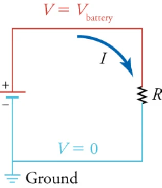
If we go from the blue wire through the battery to the red wire, the voltage increases from to .
青い導線から電池を通って赤い導線へ行けば、電圧はからへ上がる。
Likewise, if we go from the blue wire up through the resistor to the red wire, the voltage also goes from to . Thus, using Ohm’s law, we can write
同じように、青い導線から抵抗器を上って赤い導線へ行っても、電圧はからへ変わる。したがってオームの法則を使えば
Note that is measured from the bottom of the resistor to the top, meaning that the top of the resistor is at a higher voltage than the bottom of the resistor. Thus, current flows from the top of the resistor or higher voltage to the bottom of the resistor or lower voltage.
と書ける。は抵抗器の下から上へ測られており、抵抗器の上のほうが下より電圧が高いということに注意しよう。したがって、電流は抵抗器の上、すなわち電圧の高いほうから、抵抗器の下、すなわち電圧の低いほうへ流れる。
VIRTUAL PHYSICSシミュレーションBattery-Resistor Circuit電池と抵抗の回路
Use this simulation (https://openstax.org/l/21batteryresist) to better understand how resistance, voltage, and current are related. The simulation shows a battery with a resistor connected between the terminals of the battery, as in the previous figure. You can modify the battery voltage and the resistance. The simulation shows how electrons react to these changes. It also shows the atomic cores in the resistor and how they are excited and heat up as more current goes through the resistor.
このシミュレーション(https://openstax.org/l/21batteryresist)を使って、抵抗・電圧・電流の関係をよりよく理解しよう。シミュレーションは、前の図のように電池の端子の間に抵抗をつないだものを示す。電池の電圧と抵抗を変えられる。シミュレーションは電子がこの変化にどう応えるかを示す。また、抵抗の中の原子の芯も示し、抵抗を通る電流が増えるとそれがどう励起され熱くなるかを示す。
Draw the circuit diagram for the circuit, being sure to draw an arrow indicating the direction of the current. Now pick three spots along the wire. Without changing the settings, allow the simulation to run for 20 s while you count the number of electrons passing through that spot. Record the number on the circuit diagram. Now do the same thing at each of the other two spots in the circuit. What do you notice about the number of charges passing through each spot in 20 s? Remember that that current is defined as the rate that charges flow through the circuit. What does this mean about the current through the entire circuit?
この回路の回路図を描こう。電流の向きを示す矢印を必ず描くこと。次に導線に沿って三つの場所を選ぶ。設定を変えずに、シミュレーションを20秒動かし、その場所を通る電子の数を数えよう。その数を回路図に記録する。次に回路の他の二つの場所でも同じことをする。20秒間にそれぞれの場所を通る電荷の数について何に気づくか。電流が、電荷が回路を流れる割合として定められることを思い出そう。これは回路全体を流れる電流について何を意味するか。
With the voltage slider, give the battery a positive voltage. Notice that the electrons are spaced farther apart in the left wire than they are in the right wire. How does this reflect the voltage in the two wires?
電圧のつまみで、電池に正の電圧を与えよう。左の導線のほうが右の導線より電子の間隔が広いことに気づく。これは二本の導線の電圧をどう反映しているか。
a. The voltage between static charges is directly proportional to the distance between them.b. The voltage between static charges is directly proportional to square of the distance between them.
a. 静止した電荷どうしの間の電圧は、両者の距離に正比例する。b. 静止した電荷どうしの間の電圧は、両者の距離の2乗に正比例する。
c. The voltage between static charges is inversely proportional to the distance between them.d. The voltage between static charges is inversely proportional to square of the distance between them.
c. 静止した電荷どうしの間の電圧は、両者の距離に反比例する。d. 静止した電荷どうしの間の電圧は、両者の距離の2乗に反比例する。
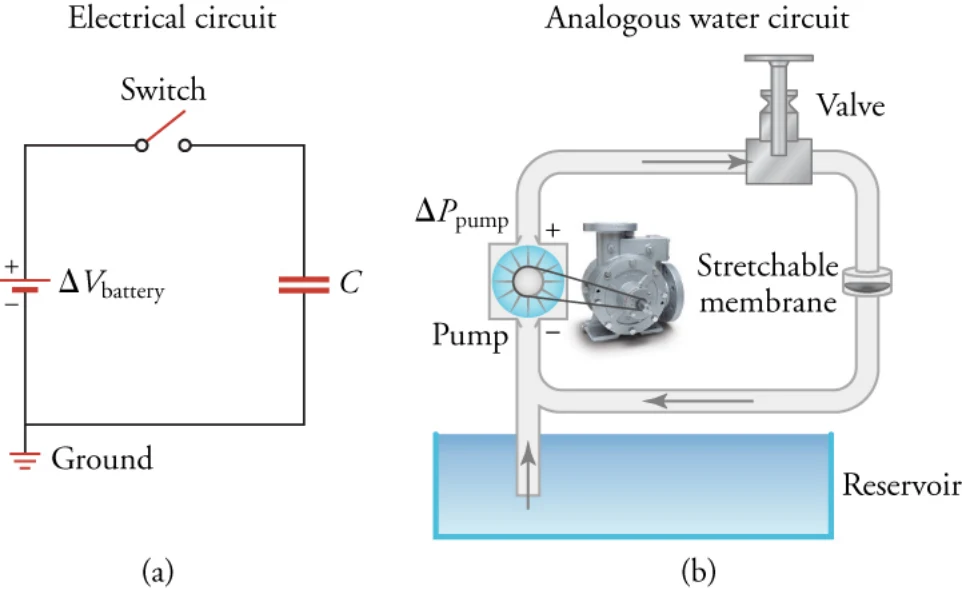
Other possible circuit elements include capacitors and switches. These are drawn as shown on the left side of Figure 19.12. A switch is a device that opens and closes the circuit, like a light switch. It is analogous to a valve in a water circuit, as shown on the right side of Figure 19.12. With the switch open, no current passes through the circuit. With the switch closed, it becomes part of the wire, so the current passes through it with no loss of voltage.
他にありうる回路の素子には、コンデンサーとスイッチがある。これらは図19.12の左側のように描かれる。スイッチは、照明のスイッチのように回路を開いたり閉じたりする装置である。図19.12の右側に示すように、水の回路のバルブにあたる。スイッチを開けば回路に電流は流れない。スイッチを閉じればそれは導線の一部になり、電圧の損失なしに電流が通る。
The capacitor is labeled C on the left of Figure 19.12. A capacitor in an electrical circuit is analogous to a flexible membrane in a water circuit. When the switch is closed in the circuit of Figure 19.12, the battery forces electrical current to flow toward the capacitor, charging the upper capacitor plate with positive charge. As this happens, the voltage across the capacitor plates increases. This is like the membrane in the water circuit: When the valve is opened, the pump forces water to flow toward the membrane, making it stretch to store the excess water. As this happens, the pressure behind the membrane increases.
図19.12の左でCと書かれているのがコンデンサーである。電気回路のコンデンサーは、水の回路のしなやかな膜にあたる。図19.12の回路でスイッチを閉じると、電池が電流をコンデンサーのほうへ流し、上のコンデンサーの板を正の電荷で帯電させる。これが起こるにつれ、コンデンサーの板の間の電圧が上がる。これは水の回路の膜と同じである。バルブを開くと、ポンプが水を膜のほうへ流し、膜は余分な水を溜めるために伸びる。これが起こるにつれ、膜の後ろの圧力が上がる。
Now if we open the switch, the capacitor holds the voltage between its plates because the charges have nowhere to go. Likewise, if we close the valve, the water has nowhere to go and the membrane maintains the water pressure in the pipe between itself and the valve.
ここでスイッチを開けば、電荷に行き場がないので、コンデンサーは板の間の電圧を保つ。同じように、バルブを閉じれば水に行き場がなく、膜は自分とバルブの間の管の水の圧力を保つ。
If the switch is closed for a long time in the electric circuit or if the valve is open for a long time in the water circuit, the current will eventually stop flowing because the capacitor or the membrane will have become completely charged. Each circuit is now in the steady state, which means that its characteristics do not change over time. In this case, the steady state is characterized by zero current, and this does not change as long as the switch or valve remains in the same position. In the steady state, no electrical current passes through the capacitor, and no water current passes through the membrane. The voltage difference between the capacitor plates will be the same as the battery voltage. In the water circuit, the pressure behind the membrane will be the same as the pressure created by the pump.
電気回路でスイッチを長く閉じたままにするか、水の回路でバルブを長く開いたままにすれば、コンデンサーや膜が完全に充電されてしまうので、やがて電流は止まる。どちらの回路もいまや定常状態にある。定常状態とは、その特徴が時間とともに変わらないことを意味する。この場合、定常状態は電流が0であることで特徴づけられ、スイッチやバルブが同じ位置にある限りこれは変わらない。定常状態では、コンデンサーを通る電流はなく、膜を通る水の流れもない。コンデンサーの板の間の電圧の差は電池の電圧と同じになる。水の回路では、膜の後ろの圧力はポンプが作る圧力と同じになる。
Although the circuit in Figure 19.12 may seem a bit pointless because all that happens when the switch is closed is that the capacitor charges up, it does show the capacitor’s ability to store charge. Thus, the capacitor serves as a reservoir for charge. This property of capacitors is used in circuits in many ways. For example, capacitors are used to power circuits while batteries are being charged. In addition, capacitors can serve as filters. To understand this, let’s go back to the water analogy. Suppose you have a water hose and are watering your garden. Your friend thinks he’s funny, and kinks the hose. While the hose is kinked, you experience no water flow. When he lets go, the water starts flowing again. If he does this really fast, you experience water-no water-water-no water, and that’s really no way to water your garden. Now imagine that the hose is filling up a big bucket, and you are watering from the bottom of the bucket. As long as you had water in your bucket to begin with and your friend doesn’t kink the water hose for too long, you would be able to water your garden without the interruptions. Your friend kinking the water hose is filtered by the big bucket’s supply of water, so it does not impact your ability to water the garden. We can think of the interruptions in the current (be it water or electrical current) as noise. Capacitors act in an analogous way as the water bucket to help filter out the noise. Capacitors have so many uses that it is very rare to find an electronic circuit that does not include some capacitors.
図19.12の回路は、スイッチを閉じてもコンデンサーが充電されるだけなので少し無意味に思えるかもしれないが、コンデンサーが電荷を蓄える能力を示してはいる。したがってコンデンサーは電荷の貯えとして働く。コンデンサーのこの性質は回路で多くのしかたに使われる。たとえばコンデンサーは、電池が充電されているあいだ回路に電力を供給するのに使われる。さらにコンデンサーはフィルターとしても働きうる。これを理解するために水の類比に戻ろう。ホースで庭に水をやっているとする。友人が面白いつもりでホースを折り曲げる。ホースが折れているあいだは水が流れない。放せばまた流れ出す。これをとても速く繰り返されれば、水が出る、出ない、出る、出ないとなり、それではとても庭に水はやれない。ここで、ホースが大きなバケツを満たしていて、あなたはバケツの底から水をやっているとしよう。はじめにバケツに水があり、友人がホースを長く折り曲げすぎない限り、途切れずに庭へ水をやれる。友人がホースを折ることは、バケツの水の貯えによって濾され、庭へ水をやる能力に影響しない。電流(水でも電気でも)の途切れを雑音と考えられる。コンデンサーは水のバケツと同じように働き、雑音を濾すのを助ける。コンデンサーの用途はあまりに多いので、コンデンサーを含まない電子回路を見つけるのはとても稀である。
What It Takes to be an Electrical Engineer Physics is used in a wide variety of fields. One field that requires a very thorough knowledge of physics is electrical engineering. An electrical engineer can work on anything from the large-scale power systems that provide power to big cities to the nanoscale electronic circuits that are found in computers and cell phones (Figure 19.13).
電気技術者になるということ 物理はきわめて幅広い分野で使われる。物理の徹底した知識を要する分野の一つが電気工学である。電気技術者は、大都市に電力を供給する大規模な電力系統から、コンピューターや携帯電話にあるナノ尺度の電子回路まで、何でも扱う(図19.13)。
In working with power companies, you can be responsible for maintaining the power grid that supplies electrical power to large areas. Although much of this work is done from an office, it is common to be called in for overtime duty after storms or other natural events. Many electrical engineers enjoy this part of the job, which requires them to race around the countryside repairing high-voltage transformers and other equipment. However, one of the more unpleasant aspects of this work is to remove the carcasses of unfortunate squirrels or other animals that have wandered into the transformers.
電力会社で働けば、広い地域に電力を供給する送電網の維持を任されうる。この仕事の多くは事務所で行われるが、嵐その他の自然の出来事のあとに残業に呼び出されるのはよくあることである。多くの電気技術者はこの部分の仕事を楽しむ。田舎を駆け回って高電圧の変圧器その他の設備を直すのである。しかし、この仕事のより不愉快な面の一つが、変圧器へ迷い込んで不幸に遭ったリスなどの動物の死骸を取り除くことである。
Other careers in electrical engineering can involve designing circuits for cell phones, which requires cramming some 10 billion transistors into an electronic chip the size of your thumbnail. These jobs can involve much work with computer simulations and can also involve fields other than electronics. For example, the 1-m-diameter lenses that are used to make these circuits (as of 2015) are so precise that they are shipped from the manufacture to the chip fabrication plant in temperature-controlled trucks to ensure that they are held within a certain temperature range. If they heat up or cool down too much, they deform ever so slightly, rendering them useless for the ultrahigh precision photolithography required to manufacture these chips.
電気工学の他の職には、携帯電話の回路の設計もありうる。それには、親指の爪ほどの大きさの電子チップに100億ものトランジスタを詰め込む必要がある。こうした仕事にはコンピューターのシミュレーションによる作業が多く、電子工学以外の分野にも関わりうる。たとえば、こうした回路を作るのに使われる直径1 mのレンズは、(2015年時点で)あまりに精密なので、決まった温度の範囲に保たれるよう、製造元からチップの工場まで温度を管理したトラックで運ばれる。温まりすぎても冷えすぎても、ごくわずかに変形し、こうしたチップの製造に必要な超高精度のフォトリソグラフィーに使えなくなってしまう。
In addition to a solid knowledge of physics, electrical engineers must above all be practical. Consider, for example, how one corporation managed to launch some anti-ballistic missiles at the White Sands Missile Test Range in New
確かな物理の知識に加え、電気技術者は何より実際的でなければならない。たとえば、1960年代にある会社がニューメキシコ州の
Mexico in the 1960s. Before launch, the skin of the missile had to be at the same voltage as the rail from which it was launched. The rail was connected to the ground by a large copper wire connected to a stake driven into the sandy earth. The missile, however, was connected by an umbilical cord to the equipment in the control shed a few meters away, which was grounded via a different grounding circuit. Before launching the missile, the voltage difference between the missile skin and the rail had to be less than 2.5 V. After an especially dry spell of weather, the missile could not be launched because the voltage difference stood at 5 V. A group of electrical engineers, including the father of your author, stood around pondering how to reduce the voltage difference. The situation was resolved when one of the engineers realized that urine contains electrolytes and conducts electricity quite well. With that, the four engineers quickly resolved the problem by urinating on the rail spike. The voltage difference immediately dropped to below 2.5 V and the missile was launched on schedule.
ホワイトサンズ・ミサイル実験場で弾道弾迎撃ミサイルを打ち上げようとしたときのことを考えよう。打ち上げ前、ミサイルの外殻は、そこから打ち上げられるレールと同じ電圧でなければならなかった。レールは、砂地に打ち込まれた杭につながる太い銅線で接地されていた。しかしミサイルは、数メートル離れた管制小屋の機器へへその緒でつながれており、その機器は別の接地の回路で接地されていた。ミサイルを打ち上げる前に、ミサイルの外殻とレールの電圧差は2.5 V未満でなければならなかった。とくに乾いた天気が続いたあと、電圧差が5 Vのままだったのでミサイルを打ち上げられなかった。本書の著者の父を含む電気技術者の一団が、どうすれば電圧差を減らせるかと考え込んでいた。技術者の一人が、尿は電解質を含み電気をかなりよく通すと気づいたことで、事態は解決した。それを聞いて四人の技術者はすぐに、レールの杭に小便をかけて問題を解決した。電圧差はただちに2.5 V未満へ下がり、ミサイルは予定どおり打ち上げられた。

VIRTUAL PHYSICSシミュレーション
Amuse yourself by building circuits of all different shapes and sizes. This simulation (https://openstax.org/l/ 21phetcirconstr) provides you with various standard circuit elements, such as batteries, AC voltage sources, resistors, capacitors, light bulbs, switches, etc. You can connect these in any configuration you like and then see the result.
いろいろな形と大きさの回路を組み立てて楽しもう。このシミュレーション(https://openstax.org/l/21phetcirconstr)は、電池、交流電圧源、抵抗、コンデンサー、電球、スイッチなど、標準的な回路の素子をいろいろ用意している。好きな配置でつなぎ、結果を見られる。
Build a circuit that starts with a resistor connected to a capacitor. Connect the free side of the resistor to the positive terminal of a battery and the free side of the capacitor to the negative terminal of the battery. Click the reset dynamics button to see how the current flows starting with no charge on the capacitor. Now right click on the resistor to change its value. When you increase the resistance, does the circuit reach the steady state more rapidly or more slowly?
抵抗にコンデンサーをつないだ回路から始めよう。抵抗の空いた側を電池の正の端子に、コンデンサーの空いた側を電池の負の端子につなぐ。「reset dynamics」を押して、コンデンサーに電荷がない状態から電流がどう流れるかを見よう。次に抵抗を右クリックしてその値を変えよう。抵抗を大きくすると、回路はより速く定常状態に達するか、それともより遅くなるか。
PhET Explorations: Circuit Construction Kit (DC only). An electronics kit in your computer! Build circuits with resistors, light bulbs, batteries, and switches. Take measurements with the realistic ammeter and voltmeter. View the circuit as a schematic diagram, or switch to a life-like view.Access multimedia content (http://openstax.org/books/physics/pages/19-2-series-circuits) When the circuit has reached the steady state, how does the voltage across the capacitor compare to the voltage of the battery? What is the voltage across the resistor?
PhET探究:回路組み立てキット(直流のみ)。あなたのコンピューターの中の電子工作キット。抵抗・電球・電池・スイッチで回路を組み立てよう。本物らしい電流計と電圧計で測定しよう。回路を回路図として見ることも、実物らしい見え方に切り替えることもできる。マルチメディア教材はこちら(http://openstax.org/books/physics/pages/19-2-series-circuits) 回路が定常状態に達したとき、コンデンサーにかかる電圧は電池の電圧とくらべてどうか。抵抗にかかる電圧はいくらか。
a. The voltage across the capacitor is greater than the voltage of the battery. In the steady state, no current flows through this circuit, so the voltage across the resistor is zero.b. The voltage across the capacitor is smaller than the voltage of the battery. In the steady state, finite current flows through this circuit, so the voltage across the resistor is finite.c. The voltage across the capacitor is the same as the voltage of the battery. In the steady state, no current flows through this circuit, so the voltage across the resistor is zero.d. The voltage across the capacitor is the same as the voltage of the battery. In the steady state, finite current flows through this circuit, so the voltage across the resistor is finite.
a. コンデンサーにかかる電圧は電池の電圧より大きい。定常状態ではこの回路に電流は流れないので、抵抗にかかる電圧は0である。b. コンデンサーにかかる電圧は電池の電圧より小さい。定常状態ではこの回路に有限の電流が流れるので、抵抗にかかる電圧は有限である。c. コンデンサーにかかる電圧は電池の電圧と同じである。定常状態ではこの回路に電流は流れないので、抵抗にかかる電圧は0である。d. コンデンサーにかかる電圧は電池の電圧と同じである。定常状態ではこの回路に有限の電流が流れるので、抵抗にかかる電圧は有限である。
Resistors in Series and Equivalent Resistance直列の抵抗と合成抵抗
638Now that we have a basic idea of how electrical circuits work, let’s see what happens in circuits with more than one circuit element. In this section, we look at resistors in series. Components connected in series are connected one after the other in the same branch of a circuit, such as the resistors connected in series on the left side of Figure 19.14.
電気回路の働きの基本が分かったので、複数の回路素子を持つ回路で何が起こるかを見よう。この節では直列の抵抗を見る。直列につながれた部品は、図19.14の左側で直列につながれた抵抗のように、回路の同じ枝の中で一つずつ順につながれている。
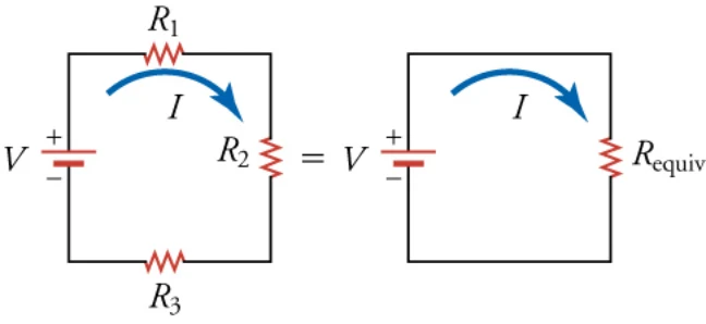
We will now try to find a single resistance that is equivalent to the three resistors in series on the left side of Figure 19.14. An equivalent resistor is a resistor that has the same resistance as the combined resistance of a set of other resistors. In other words, the same current will flow through the left and right circuits in Figure 19.14 if we use the equivalent resistor in the right circuit.
ここで、図19.14の左側の直列の三つの抵抗と同等な一つの抵抗を求めてみよう。等価な抵抗器とは、一組の他の抵抗器を合わせた抵抗と同じ抵抗を持つ抵抗器である。言い換えれば、図19.14の右の回路に等価な抵抗器を使えば、左と右の回路に同じ電流が流れる。
According to Ohm’s law, the voltage drop V across a resistor when a current flows through it is where I is the current in amperes (A) and R is the resistance in ohms ( ). Another way to think of this is that V is the voltage necessary to make a current I flow through a resistance R. Applying Ohm’s law to each resistor on the left circuit of Figure 19.14, we find that the voltage drop across is , that across is , and that across is . The sum of these voltages equals the voltage output of the battery, that is
オームの法則によれば、電流が流れるときに抵抗にかかる電圧の降下Vはである。ここでIはアンペア(A)で表した電流、Rはオーム()で表した抵抗である。これを別の見方で考えると、Vは抵抗Rに電流Iを流すのに必要な電圧である。図19.14の左の回路のそれぞれの抵抗にオームの法則を当てはめると、にかかる電圧の降下は、にかかるのは、にかかるのはである。これらの電圧の和が電池の出力電圧に等しい。すなわち
You may wonder why voltages must add up like this. One way to understand this is to go once around the circuit and add up the successive changes in voltage. If you do this around a loop and get back to the starting point, the total change in voltage should be zero, because you end up at the same place that you started. To better understand this, consider the analogy of going for a stroll through some hilly countryside. If you leave your car and walk around, then come back to your car, the total height you gained in your stroll must be the same as the total height you lost, because you end up at the same place as you started. Thus, the gravitational potential energy you gain must be the same as the gravitational potential energy you lose. The same reasoning holds for voltage in going around an electric circuit. Let’s apply this reasoning to the left circuit in Figure 19.14. We start just below the battery and move up through the battery, which contributes a voltage gain of . Next, we got through the resistors. The voltage drops by in going through resistor , by in going through resistor , and by in going through resistor . After going through resistor , we arrive back at the starting point, so we add up these four changes in voltage and set the sum equal to zero. This gives
なぜ電圧がこのように足し合わされるのか不思議に思うかもしれない。これを理解する一つのやり方は、回路を一周して、次々の電圧の変化を足し合わせることである。輪を一周して出発点へ戻れば、出発した同じ場所に行き着くので、電圧の変化の合計は0でなければならない。これをよりよく理解するために、起伏のある田舎を散歩する類比を考えよう。車を降りて歩き回り、それから車へ戻れば、散歩で登った高さの合計は下った高さの合計と同じでなければならない。出発した同じ場所に行き着くからである。したがって、得た重力による位置エネルギーは失った重力による位置エネルギーと同じでなければならない。同じ理屈が、電気回路を一周するときの電圧にも当てはまる。この理屈を図19.14の左の回路に当てはめよう。電池のすぐ下から出発して電池を上っていくと、の電圧の上昇が加わる。次に抵抗を通っていく。電圧は抵抗を通るとき、抵抗を通るとき、抵抗を通るときだけ下がる。抵抗を通ったあと、出発点へ戻るので、この四つの電圧の変化を足して和を0とおく。これから
which is the same as the previous equation. Note that the minus signs in front of are because these are voltage drops, whereas is a voltage rise.
が得られ、これは前の式と同じである。の前のマイナス符号は、これらが電圧の降下であるためであり、は電圧の上昇であることに注意しよう。
Ohm’s law tells us that , , and . Inserting these values into equation gives
オームの法則は、、と教える。これらの値を式に入れると
Applying this same logic to the right circuit in Figure 19.14 gives
が得られる。同じ理屈を図19.14の右の回路に当てはめると
Dividing the equation by , we get
となる。式をで割ると
This shows that the equivalent resistance for a series of resistors is simply the sum of the resistances of each resistor. In general, N resistors connected in series can be replaced by an equivalent resistor with a resistance of
が得られる。これは、直列の抵抗の合成抵抗が、単にそれぞれの抵抗の和であることを示す。一般に、直列につないだN個の抵抗は、次の抵抗を持つ一つの等価な抵抗で置き換えられる。
Resistors in Series This video discusses the basic concepts behind interpreting circuit diagrams and then shows how to calculate the equivalent resistance for resistors in series.
直列の抵抗 この動画は、回路図を読む背後にある基本の考えを論じ、それから直列の抵抗の合成抵抗をどう計算するかを示す。
Resistors in series | Circuits | Physics | Khan Academy (https://www.openstax.org/l/02resistseries)
直列の抵抗|回路|物理|カーンアカデミー(https://www.openstax.org/l/02resistseries)
GRASP CHECK True or false—In a circuit diagram, we can assume that the voltage is the same at every point in a given wire.a. falseb. true
理解の確認 正誤問題——回路図では、決まった一本の導線のどの点でも電圧は同じだとみなしてよい。a. 誤b. 正
Calculation of Equivalent Resistance In the left circuit of the previous figure, suppose the voltage rating of the battery is 12 V, and the resistances are
合成抵抗の計算 前の図の左の回路で、電池の定格電圧が12 V、抵抗が
. (a) What is the equivalent resistance? (b) What is the current through the circuit? Strategy FOR (A)
だとする。(a)合成抵抗はいくらか。(b)回路を流れる電流はいくらか。 (a)の方針
Use the equation for the equivalent resistance of resistors connected in series. Because the circuit has three resistances, we only need to keep three terms, so it takes the form
直列につないだ抵抗の合成抵抗の式を使う。この回路には三つの抵抗があるので、三つの項だけを残せばよく、式は次の形になる。
Solution for (a)(a)の解答
Inserting the given resistances into the equation above gives
与えられた抵抗を上の式に入れると
Discussion for (a)(a)の考察
We can thus replace the three resistors with a single 20- resistor.
したがって三つの抵抗を、一つの20 の抵抗で置き換えられる。
Strategy FOR (B)(b)の方針
Apply Ohm’s law to the circuit on the right side of the previous figure with the equivalent resistor of 20 .
前の図の右側の、20 の等価な抵抗を持つ回路にオームの法則を当てはめる。
Solution for (b)(b)の解答
The voltage drop across the equivalent resistor must be the same as the voltage rise in the battery. Thus, Ohm’s law gives
等価な抵抗にかかる電圧の降下は、電池の電圧の上昇と同じでなければならない。したがってオームの法則から
Discussion for (b)(b)の考察
To check that this result is reasonable, we calculate the voltage drop across each resistor and verify that they add up to the voltage rating of the battery. The voltage drop across each resistor is
この結果が妥当かを確かめるために、それぞれの抵抗にかかる電圧の降下を計算し、その和が電池の定格電圧になることを確かめる。それぞれの抵抗にかかる電圧の降下は
Adding these voltages together gives
これらの電圧を足すと
which is the voltage rating of the battery.
となり、これは電池の定格電圧である。
Strategy方針
The four resistances in this circuit are connected in series, so we know that they must add up to give the equivalent resistance. We can use this to find the unknown resistance .
この回路の四つの抵抗は直列につながれているので、それらを足すと合成抵抗になるはずである。これを使って未知の抵抗を求められる。
Solution解答
For four resistances in series, the equation for the equivalent resistance of resistors in series takes the form
直列の四つの抵抗では、直列の抵抗の合成抵抗の式は次の形になる。
Solving for R3 and inserting the known values gives
R3について解き、分かっている値を入れると
Discussion考察
The equivalent resistance of a circuit can be measured with an ohmmeter. This is sometimes useful for determining the effective resistance of elements whose resistance is not marked on the element.
回路の合成抵抗は抵抗計で測れる。素子に抵抗値が書かれていない場合に、その実効の抵抗を決めるのに役立つことがある。
Check your Understanding理解の確認
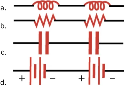
8 .
8

What circuit element is represented in the figure above?a. a batteryb. a resistor
上の図に描かれている回路の素子はどれか。a. 電池b. 抵抗器
c. a capacitord. an inductor
c. コンデンサーd. コイル
9How would a diagram of two resistors connected in series appear?
9直列につないだ二つの抵抗の図はどのようになるか。