第16章鏡とレンズMirrors and Lenses原書 p.495–540
16.3 Lenses16.3 レンズ
SECTION LEARNING OBJECTIVES By the end of this section, you will be able to do the following:
この節の学習目標 この節を終えると、次のことができるようになる。
• Describe and predict image formation and magnification as a consequence of refraction through convex and concave lenses, use ray diagrams to confirm image formation, and discuss how these properties of lenses determine their applications• Explain how the human eye works in terms of geometric optics• Perform calculations, based on the thin-lens equation, to determine image and object distances, focal length, and image magnification, and use these calculations to confirm values determined from ray diagrams
・凸レンズと凹レンズを通る屈折の結果としての像のでき方と倍率を述べて予測し、光線図で像のでき方を確かめ、レンズのこうした性質がその用途をどう決めるかを論じる・人の目の働きを幾何光学の言葉で説明する・薄レンズの式にもとづいて計算を行い、像と物までの距離、焦点距離、像の倍率を求め、その計算で光線図から求めた値を確かめる
Section Key Termsこの節の重要語
aberrationchromatic aberrationconcave lensconverging lensconvex lensdiverging lenseyepieceobjectiveocularparfocal
収差色収差凹レンズ集束レンズ凸レンズ発散レンズ接眼レンズ対物レンズ接眼部の同焦点の
Characteristics of Lensesレンズの特徴
Lenses are found in a huge array of optical instruments, ranging from a simple magnifying glass to the eye to a camera’s zoom lens. In this section, we use the law of refraction to explore the properties of lenses and how they form images.
レンズは、単純な虫めがねから目、カメラのズームレンズまで、実に幅広い光学器械に見られる。この節では、屈折の法則を使ってレンズの性質と像のでき方を探る。
Some of what we learned in the earlier discussion of curved mirrors also applies to the study of lenses. Concave, convex, focal point F, and focal length f have the same meanings as before, except each measurement is made from the center of the lens instead of the surface of the mirror. The convex lens shown in Figure 16.25 has been shaped so that all light rays that enter it parallel to its central axis cross one another at a single point on the opposite side of the lens. The central axis, or axis, is defined to be a line normal to the lens at its center. Such a lens is called a converging lens because of the converging effect it has on light rays. An expanded view of the path of one ray through the lens is shown in Figure 16.25 to illustrate how the ray changes direction both as it enters and as it leaves the lens. Because the index of refraction of the lens is greater than that of air, the ray moves toward the perpendicular as it enters and away from the perpendicular as it leaves. (This is in accordance with the law of refraction.) As a result of the shape of the lens, light is thus bent toward the axis at both surfaces.
曲面鏡について先に論じたことの一部は、レンズの学習にも当てはまる。凹、凸、焦点F、焦点距離fは以前と同じ意味を持つが、どの測定も鏡の面ではなくレンズの中心から行われる。図16.25の凸レンズは、中心軸に平行に入るすべての光線が、レンズの反対側の一点で互いに交わるような形に作られている。中心軸、すなわち軸は、レンズの中心で面に垂直な線と定義される。そのようなレンズは、光線を集める働きから集束レンズと呼ばれる。光線がレンズに入るときと出るときの両方で向きを変える様子を示すために、レンズを通る一本の光線の道筋の拡大図を図16.25に示す。レンズの屈折率は空気より大きいので、光線は入るとき垂線のほうへ、出るとき垂線から離れるほうへ動く。(これは屈折の法則にかなう。)レンズの形の結果として、光は両方の面で軸のほうへ曲げられる。
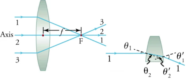
Note that rays from a light source placed at the focal point of a converging lens emerge parallel from the other side of the lens. You may have heard of the trick of using a converging lens to focus rays of sunlight to a point. Such a concentration of light energy can produce enough heat to ignite paper.
集束レンズの焦点に置かれた光源からの光線は、レンズの反対側から平行になって出ていくことに注意しよう。集束レンズで日光を一点に集める手品を聞いたことがあるかもしれない。そのような光のエネルギーの集中は、紙を燃やすのに十分な熱を生みうる。
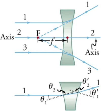
Figure 16.26 shows a concave lens and the effect it has on rays of light that enter it parallel to its axis (the path taken by ray 2 in the figure is the axis of the lens). The concave lens is a diverging lens because it causes the light rays to bend away (diverge) from its axis. In this case, the lens has been shaped so all light rays entering it parallel to its axis appear to originate from the same point, F, defined to be the focal point of a diverging lens. The distance from the center of the lens to the focal point is again called the focal length, or “ƒ,” of the lens. Note that the focal length of a diverging lens is defined to be negative. An expanded view of the path of one ray through the lens is shown in Figure 16.26 to illustrate how the shape of the lens, together with the law of refraction, causes the ray to follow its particular path and diverge.
図16.26は凹レンズと、それが軸に平行に入った光線に及ぼす効果を示す(図の光線2がたどる道筋がレンズの軸である)。凹レンズは、光線を軸から離れるほうへ曲げる(発散させる)ので発散レンズである。この場合、レンズは、軸に平行に入ったすべての光線が同じ点Fから出ているように見える形に作られており、この点が発散レンズの焦点と定義される。レンズの中心から焦点までの距離を、これもまた焦点距離、すなわちレンズのfという。発散レンズの焦点距離は負と定義されることに注意しよう。レンズの形と屈折の法則が相まって光線がその特有の道筋をたどって発散する様子を示すために、レンズを通る一本の光線の道筋の拡大図を図16.26に示す。
The power, P, of a lens is very easy to calculate. It is simply the reciprocal of the focal length, expressed in meters
レンズの度数Pはとても簡単に計算できる。メートルで表した焦点距離の逆数にすぎない。
The units of power are diopters, D, which are expressed in reciprocal meters. If the focal length is negative, as it is for the diverging lens in Figure 16.26, then the power is also negative.
度数の単位はジオプター(D)で、メートルの逆数で表される。図16.26の発散レンズのように焦点距離が負なら、度数も負である。
In some circumstances, a lens forms an image at an obvious location, such as when a movie projector casts an image onto a screen. In other cases, the image location is less obvious. Where, for example, is the image formed by eyeglasses? We use ray tracing for thin lenses to illustrate how they form images, and we develop equations to describe the image-formation quantitatively. These are the rules for ray tracing:
映写機がスクリーンに像を映すときのように、レンズが像を作る場所が明らかな場合もある。像の場所があまり明らかでない場合もある。たとえば眼鏡が作る像はどこにあるのか。薄レンズについて光線を追う方法を使って像のでき方を示し、像のでき方を量的に述べる式を作る。光線を追う規則は次のとおりである。
1. A ray entering a converging lens parallel to its axis passes through the focal point, F, of the lens on the other side2. A ray entering a diverging lens parallel to its axis seems to come from the focal point, F, on the side of the entering ray3. A ray passing through the center of either a converging or a diverging lens does not change direction4. A ray entering a converging lens through its focal point exits parallel to its axis5. A ray that enters a diverging lens by heading toward the focal point on the opposite side exits parallel to the axis
1. 集束レンズに軸に平行に入った光線は、反対側でレンズの焦点Fを通る2. 発散レンズに軸に平行に入った光線は、入った側の焦点Fから来たように見える3. 集束レンズでも発散レンズでも、中心を通る光線は向きを変えない4. 集束レンズに焦点を通って入った光線は、軸に平行に出ていく5. 反対側の焦点へ向かって発散レンズに入った光線は、軸に平行に出ていく
Consider an object some distance away from a converging lens, as shown in Figure 16.27. To find the location and size of the image formed, we trace the paths of select light rays originating from one point on the object. In this example, the originating point is the top of a woman’s head. Figure 16.27 shows three rays from the top of the object that can be traced using the ray-tracing rules just listed. Rays leave this point traveling in many directions, but we concentrate on only a few, which have paths that are easy to trace. The first ray is one that enters the lens parallel to its axis and passes through the focal point on the other side (rule 1). The second ray passes through the center of the lens without changing direction (rule 3). The third ray passes through the nearer focal point on its way into the lens and leaves the lens parallel to its axis (rule 4). All rays that come from the same point on the top of the person’s head are refracted in such a way as to cross at the same point on the other side of the lens. The image of the top of the person’s head is located at this point. Rays from another point on the object, such as the belt buckle, also cross at another common point, forming a complete image, as shown. Although three rays are traced in Figure 16.27, only two are necessary to locate the image. It is best to trace rays for which there are simple ray-tracing rules. Before applying ray tracing to other situations, let us consider the example shown in Figure 16.27 in more detail.
図16.27のように、集束レンズからいくらか離れたところに物があるとしよう。できる像の位置と大きさを求めるために、物の上の一点から出る選ばれた光線の道筋を追う。この例では、出発点は女性の頭の頂上である。図16.27は、いま挙げた光線を追う規則で追える、物の頂上からの三本の光線を示す。光線はこの点から多くの向きへ出ていくが、道筋を追いやすい少数のものだけに集中する。一本目は、軸に平行にレンズに入り、反対側の焦点を通る光線である(規則1)。二本目は、向きを変えずにレンズの中心を通る光線である(規則3)。三本目は、レンズに入る途中で手前の焦点を通り、レンズから軸に平行に出ていく光線である(規則4)。人の頭の頂上の同じ点から来る光線はすべて、レンズの反対側の同じ点で交わるように屈折する。人の頭の頂上の像はこの点にできる。ベルトの留め金など、物の別の点から来る光線もまた別の共通の点で交わり、図のように完全な像を作る。図16.27では三本の光線を追っているが、像の位置を突き止めるには二本で足りる。単純な光線追跡の規則がある光線を追うのが一番よい。他の場面に光線追跡を応用する前に、図16.27の例をもう少し詳しく考えよう。
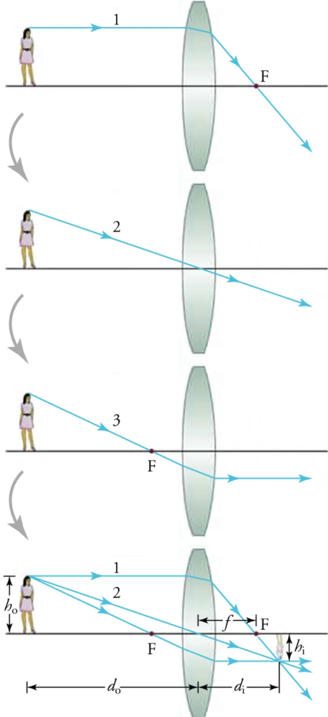
The image formed in Figure 16.27 is a real image—meaning, it can be projected. That is, light rays from one point on the object actually cross at the location of the image and can be projected onto a screen, a piece of film, or the retina of an eye.
図16.27でできる像は実像である。すなわち投影できる。物の上の一点からの光線が像の位置で実際に交わり、スクリーン、フィルム、目の網膜に投影できる。
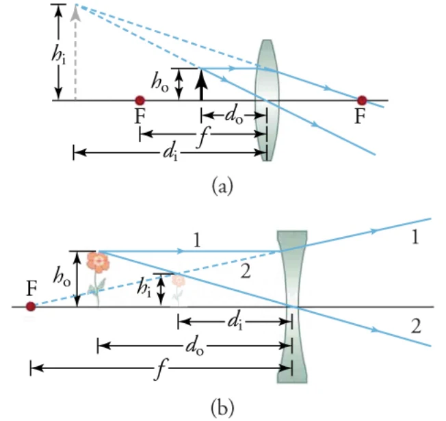
In Figure 16.27, the object distance, do, is greater than f. Now we consider a ray diagram for a convex lens where do< f, and another diagram for a concave lens.
図16.27では、物までの距離doはfより大きい。次に、do < fの凸レンズの光線図と、凹レンズの光線図を考える。
VIRTUAL PHYSICSシミュレーションGeometric Optics幾何光学
Access multimedia content (http://openstax.org/books/physics/pages/16-3-lenses) This animation shows you how the image formed by a convex lens changes as you change object distance, curvature radius, refractive index, and diameter of the lens. To begin, choose Principal Rays in the upper left menu and then try varying some of the parameters indicated at the upper center. Show Help supplies a few helpful labels.
マルチメディア教材はこちら(http://openstax.org/books/physics/pages/16-3-lenses) このアニメーションは、物までの距離、曲率半径、屈折率、レンズの直径を変えると、凸レンズが作る像がどう変わるかを示す。まず左上のメニューで「主光線」を選び、それから上の中央にあるいくつかの値を変えてみよう。「ヘルプを表示」で役に立つ表示がいくつか出る。
PhET Explorations: Geometric Optics How does a lens form an image? See how light rays are refracted by a lens. Watch how the image changes when you adjust the focal length of the lens, move the object, move the lens, or move the screen.How does the focal length, , change with an increasing radius of curvature? How does change with an increasing refractive index?
PhET探究:幾何光学 レンズはどうやって像を作るのか。光線がレンズでどう屈折するかを見よう。レンズの焦点距離を変えたり、物を動かしたり、レンズを動かしたり、スクリーンを動かしたりすると、像がどう変わるかを見よう。曲率半径を大きくすると焦点距離はどう変わるか。屈折率を大きくするとはどう変わるか。
a. The focal length increases in both cases: when the radius of curvature and the refractive index increase.b. The focal length decreases in both cases: when the radius of curvature and the refractive index increase.c. The focal length increases when the radius of curvature increases; it decreases when the refractive index increases.d. The focal length decreases when the radius of curvature increases; it increases in when the refractive index increases.
a. 曲率半径を大きくしても屈折率を大きくしても、どちらの場合も焦点距離は大きくなる。b. 曲率半径を大きくしても屈折率を大きくしても、どちらの場合も焦点距離は小さくなる。c. 曲率半径を大きくすると焦点距離は大きくなり、屈折率を大きくすると小さくなる。d. 曲率半径を大きくすると焦点距離は小さくなり、屈折率を大きくすると大きくなる。
The examples in Figure 16.27 and Figure 16.28 represent the three possible cases—case 1, case 2, and case 3—summarized in Table 16.3. In the table, m is magnification; the other symbols have the same meaning as they did for curved mirrors.
図16.27と図16.28の例は、表16.3にまとめた三つのありうる場合——場合1、場合2、場合3——を表している。表でmは倍率であり、他の記号は曲面鏡のときと同じ意味を持つ。
SNAP LAB身近な実験Focal Length焦点距離
Temperature extremes—Very hot or very cold temperatures are encountered in this lab that can cause burns. Use protective mitts, eyewear, and clothing when handling very hot or very cold objects. Notify your teacher immediately of any burns.EYE SAFETY—Looking at the Sun directly can cause permanent eye damage. Do not look at the Sun through any lens.
極端な温度——この実験ではやけどを起こしうるきわめて高い、あるいは低い温度に出会う。とても熱い、あるいはとても冷たい物を扱うときは保護手袋・保護眼鏡・保護衣を使うこと。やけどをしたらただちに先生に知らせること。目の安全——太陽を直接見ると目に永久の損傷を与えうる。どんなレンズを通しても太陽を見ないこと。
• Several lenses• A sheet of white paper• A ruler or tape measure
・レンズ数枚・白い紙一枚・定規か巻き尺
Instructions
手引き
Procedure手順
1. Find several lenses and determine whether they are converging or diverging. In general, those that are thicker near the edges are diverging and those that are thicker near the center are converging.2. On a bright, sunny day take the converging lenses outside and try focusing the sunlight onto a sheet of white paper.3. Determine the focal lengths of the lenses. Have one partner slowly move the lens toward and away from the paper until you find the distance at which the light spot is at its brightest. Have the other partner measure the distance from the lens to the bright spot. Be careful, because the paper may start to burn, depending on the type of lens.
1. レンズを数枚見つけ、集束レンズか発散レンズかを判断する。一般に、縁の近くが厚いものが発散レンズ、中心の近くが厚いものが集束レンズである。2. 晴れて明るい日に集束レンズを外へ持ち出し、日光を白い紙に集めてみる。3. レンズの焦点距離を求める。一人がレンズをゆっくり紙に近づけたり遠ざけたりして、光の点が最も明るくなる距離を見つける。もう一人がレンズから明るい点までの距離を測る。レンズの種類によっては紙が燃え始めることがあるので気をつけること。
True or false—The bright spot that appears in focus on the paper is an image of the Sun.
正誤問題——紙の上に焦点を結んで現れる明るい点は太陽の像である。
a. Trueb. False
a. 正b. 誤
Image formation by lenses can also be calculated from simple equations. We learn how these calculations are carried out near the end of this section.
レンズによる像のでき方は、単純な式からも計算できる。この節の終わり近くで、その計算のやり方を学ぶ。
Some common applications of lenses with which we are all familiar are magnifying glasses, eyeglasses, cameras, microscopes, and telescopes. We take a look at the latter two examples, which are the most complex. We have already seen the design of a telescope that uses only mirrors in Figure 16.12. Figure 16.29 shows the design of a telescope that uses two lenses. Part (a) of the figure shows the design of the telescope used by Galileo. It produces an upright image, which is more convenient for many applications. Part (b) shows an arrangement of lenses used in many astronomical telescopes. This design produces an inverted image, which is less of a problem when viewing celestial objects.
私たちがみな知っているレンズの身近な応用が、虫めがね、眼鏡、カメラ、顕微鏡、望遠鏡である。ここでは最も複雑な後ろの二つを見ていく。鏡だけを使う望遠鏡の設計は図16.12ですでに見た。図16.29は二枚のレンズを使う望遠鏡の設計を示す。図の(a)はガリレオが使った望遠鏡の設計である。これは正立の像を作り、多くの用途でより便利である。(b)は多くの天体望遠鏡で使われるレンズの配置を示す。この設計は倒立の像を作るが、天体を見るときにはあまり問題にならない。
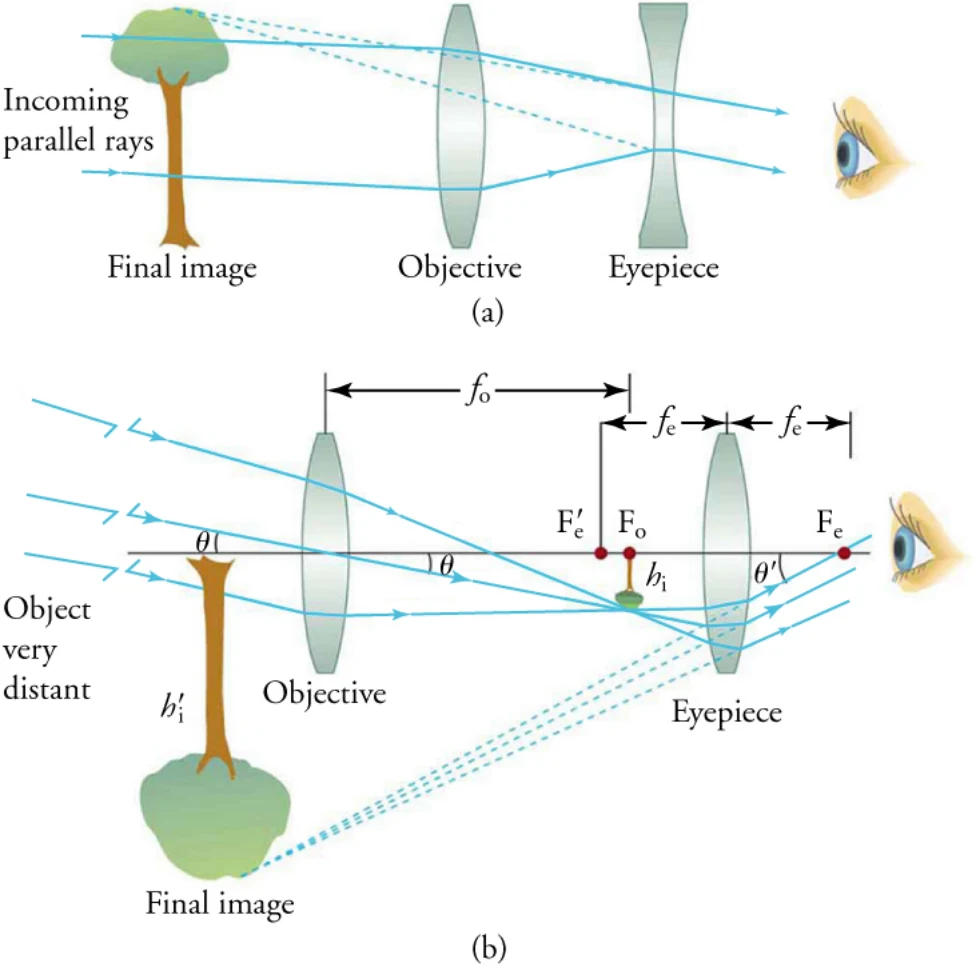
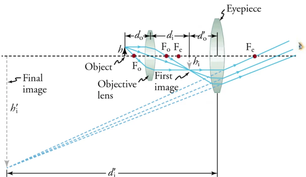
Figure 16.30 shows the path of light through a typical microscope. Microscopes were first developed during the early 1600s by eyeglass makers in the Netherlands and Denmark. The simplest compound microscope is constructed from two convex lenses, as shown schematically in Figure 16.30. The first lens is called the objective lens; it has typical magnification values from 5 to 100 . In standard microscopes, the objectives are mounted such that when you switch between them, the sample remains in focus. Objectives arranged in this way are described as parfocal. The second lens, the eyepiece, also referred to as the ocular, has several lenses that slide inside a cylindrical barrel. The focusing ability is provided by the movement of both the objective lens and the eyepiece. The purpose of a microscope is to magnify small objects, and both lenses contribute to the final magnification. In addition, the final enlarged image is produced in a location far enough from the observer to be viewed easily because the eye cannot focus on objects or images that are too close.
図16.30に、典型的な顕微鏡を通る光の道筋を示す。顕微鏡は1600年代の初めに、オランダとデンマークの眼鏡職人によって最初に作られた。最も単純な複式顕微鏡は、図16.30に模式的に示すように、二枚の凸レンズでできている。一枚目のレンズを対物レンズといい、典型的な倍率は5から100である。標準の顕微鏡では、切り替えても試料の焦点が合ったままになるように対物レンズが取り付けられている。このように配置された対物レンズは同焦点であるという。二枚目のレンズである接眼レンズ(オキュラーともいう)は、円筒の鏡筒の中を滑る複数のレンズを持つ。焦点を合わせる働きは、対物レンズと接眼レンズの両方の移動によって与えられる。顕微鏡の目的は小さな物を拡大することであり、両方のレンズが最終の倍率に寄与する。さらに、目は近すぎる物や像には焦点を合わせられないので、最終の拡大された像は、観測者から見やすいだけ離れた場所に作られる。
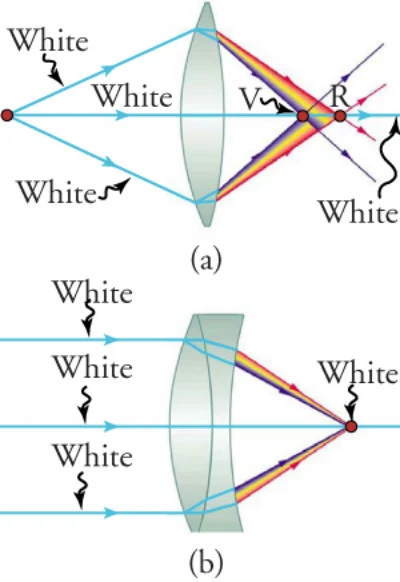
Real lenses behave somewhat differently from how they are modeled using rays diagrams or the thin-lens equations. Real lenses produce aberrations. An aberration is a distortion in an image. There are a variety of aberrations that result from lens size, material, thickness, and the position of the object. One common type of aberration is chromatic aberration, which is related to color. Because the index of refraction of lenses depends on color, or wavelength, images are produced at different places and with different magnifications for different colors. The law of reflection is independent of wavelength, so mirrors do not have this problem. This result is another advantage for the use of mirrors in optical systems such as telescopes.
実際のレンズは、光線図や薄レンズの式でモデル化されるのとはいくぶん違ったふるまいをする。実際のレンズは収差を生む。収差とは像の歪みである。レンズの大きさ・材料・厚さ、そして物の位置から生じる収差にはさまざまなものがある。よくある型の収差の一つが、色に関わる色収差である。レンズの屈折率は色、すなわち波長によるので、色ごとに違う場所に違う倍率で像ができる。反射の法則は波長によらないので、鏡にはこの問題がない。この結果は、望遠鏡のような光学系で鏡を使うもう一つの利点である。
Figure 16.31(a) shows chromatic aberration for a single convex lens, and its partial correction with a two-lens system. The index of refraction of the lens increases with decreasing wavelength, so violet rays are refracted more than red rays, and are thus focused closer to the lens. The diverging lens corrects this in part, although it is usually not possible to do so completely. Lenses made of different materials and with different dispersions may be used. For example, an achromatic doublet consisting of a converging lens made of crown glass in contact with a diverging lens made of flint glass can reduce chromatic aberration dramatically (Figure 16.31(b)).
図16.31(a)は、一枚の凸レンズの色収差と、二枚のレンズの系によるその部分的な補正を示す。レンズの屈折率は波長が短くなるにつれて大きくなるので、紫の光線は赤の光線より大きく屈折し、したがってレンズにより近いところに焦点を結ぶ。発散レンズがこれを部分的に補正するが、ふつう完全に補正することはできない。違う材料でできた、分散の違うレンズを使うこともできる。たとえば、クラウンガラスでできた集束レンズとフリントガラスでできた発散レンズを貼り合わせた色消しダブレットは、色収差を劇的に減らせる(図16.31(b))。
Physics of the Eye目の物理
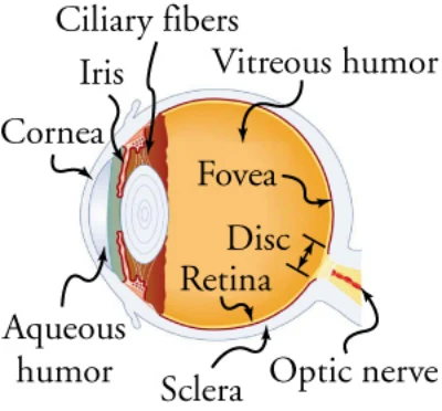
The eye is perhaps the most interesting of all optical instruments. It is remarkable in how it forms images and in the richness of detail and color they eye can detect. However, our eyes commonly need some correction to reach what is called normal vision, but should be called ideal vision instead. Image formation by our eyes and common vision correction are easy to analyze using geometric optics. Figure 16.32 shows the basic anatomy of the eye. The cornea and lens form a system that, to a good approximation, acts as a single thin lens. For clear vision, a real image must be projected onto the light-sensitive retina, which lies at a fixed distance from the lens. The lens of the eye adjusts its power to produce an image on the retina for objects at different distances. The center of the image falls on the fovea, which has the greatest density of light receptors and the greatest acuity (sharpness) in the visual field. There are no receptors at the place where the optic nerve meets the eye, which is called the blind spot. An image falling on this spot cannot be seen. The variable opening (or pupil) of the eye along with chemical adaptation allows the eye to detect light intensities from the lowest observable to 1010 times greater (without damage). Ten orders of magnitude is an incredible range of detection. Our eyes perform a vast number of functions, such as sense direction, movement, sophisticated colors, and distance. Processing of visual nerve impulses begins with interconnections in the retina and continues in the brain. The optic nerve conveys signals received by the eye to the brain.
目はおそらくあらゆる光学器械の中で最も興味深い。像の作り方も、目が感じ取れる細部と色の豊かさも、驚くべきものである。しかし私たちの目は、正常視と呼ばれる——本当は理想的な視力と呼ぶべき——状態に達するのに、たいてい何らかの補正を必要とする。目による像のでき方と、よくある視力の補正は、幾何光学で簡単に分析できる。図16.32に目の基本的な構造を示す。角膜と水晶体は、よい近似で一枚の薄レンズとしてはたらく系を作る。はっきり見えるためには、水晶体から決まった距離にある光に敏感な網膜に実像が投影されねばならない。目の水晶体は、違う距離にある物について網膜に像を作るように度数を調節する。像の中心は中心窩に落ちる。そこは光の受容器の密度が最も高く、視野の中で最も鋭い(はっきりした)ところである。視神経が目に接する場所には受容器がなく、そこは盲点と呼ばれる。この点に落ちた像は見えない。目の可変の開口(すなわち瞳孔)と化学的な順応のおかげで、目は観測できる最も低い明るさから、その1010倍の明るさまで(損傷を受けずに)感じ取れる。10桁というのは信じがたい検出の幅である。私たちの目は、向き・動き・込み入った色・距離を感じ取るなど、実に多くの働きをする。視神経の信号の処理は網膜での相互接続から始まり、脳へと続く。視神経は目が受け取った信号を脳へ伝える。
Refractive indices are crucial to image formation using lenses. Table 16.4 shows refractive indices relevant to the eye. The biggest change in the refractive index—and the one that causes the greatest bending of rays—occurs at the cornea rather than the lens. The ray diagram in Figure 16.33 shows image formation by the cornea and lens of the eye. The rays bend according to the refractive indices provided in Table 16.4. The cornea provides about two-thirds of the magnification of the eye because the speed of light changes considerably while traveling from air into the cornea. The lens provides the remaining magnification needed to produce an image on the retina. The cornea and lens can be treated as a single thin lens, although the light rays pass through several layers of material (such as the cornea, aqueous humor, several layers in the lens, and vitreous humor), changing direction at each interface. The image formed is much like the one produced by a single convex lens. This result is a case 1 image. Images formed in the eye are inverted, but the brain inverts them once more to make them seem upright.
屈折率はレンズによる像のでき方に決定的である。表16.4に目に関わる屈折率を示す。屈折率の変化が最も大きく——したがって光線が最も大きく曲がるのは——水晶体ではなく角膜である。図16.33の光線図は、目の角膜と水晶体による像のでき方を示す。光線は表16.4の屈折率に従って曲がる。空気から角膜へ進むときに光の速さが大きく変わるので、角膜が目の倍率のおよそ3分の2を担っている。水晶体は、網膜に像を作るのに必要な残りの倍率を与える。光線は(角膜・房水・水晶体の何層か・硝子体といった)いくつもの層を通り抜け、境目ごとに向きを変えるが、角膜と水晶体は一枚の薄レンズとして扱える。できる像は、一枚の凸レンズが作る像とよく似ている。これは場合1の像である。目にできる像は倒立しているが、脳がそれをもう一度ひっくり返して正立に見えるようにしている。
*The index of refraction varies throughout the lens and is greatest at its center. TABLE 16.4 Refractive Indices Relevant to the Eye
*屈折率は水晶体の中で場所によって変わり、中心で最も大きい。 表16.4 目に関わる屈折率
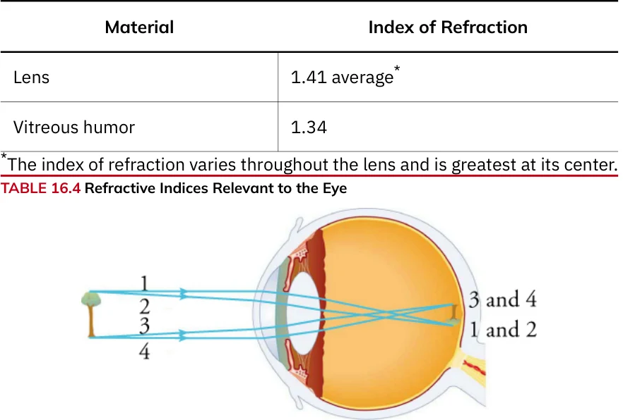
FIGURE 16.33 An image is formed on the retina, with light rays converging most at the cornea and on entering and exiting the lens. Rays from the top and bottom of the object are traced and produce an inverted real image on the retina. The distance to the object is drawn smaller than scale.
図16.33 網膜に像ができる。光線は角膜で、また水晶体に入るときと出るときに最も大きく集まる。物の上端と下端からの光線を追うと、網膜に倒立した実像ができる。物までの距離は縮尺より小さく描いてある。
As noted, the image must fall precisely on the retina to produce clear vision—that is, the image distance, di, must equal the lens-to-retina distance. Because the lens-to-retina distance does not change, di must be the same for objects at all distances. The eye manages to vary the distance by varying the power (and focal length) of the lens to accommodate for objects at various distances. In Figure 16.33, you can see the small ciliary muscles above and below the lens that change the shape of the lens and, thus, the focal length.
述べたとおり、はっきり見えるためには像がちょうど網膜に落ちねばならない——すなわち像までの距離diは、水晶体から網膜までの距離に等しくなければならない。水晶体から網膜までの距離は変わらないので、どの距離の物についてもdiは同じでなければならない。目は、水晶体の度数(と焦点距離)を変えることでいろいろな距離の物に合わせ、この距離を保つ。図16.33で、水晶体の上下にある小さな毛様体筋が、水晶体の形を、したがって焦点距離を変えているのが見える。
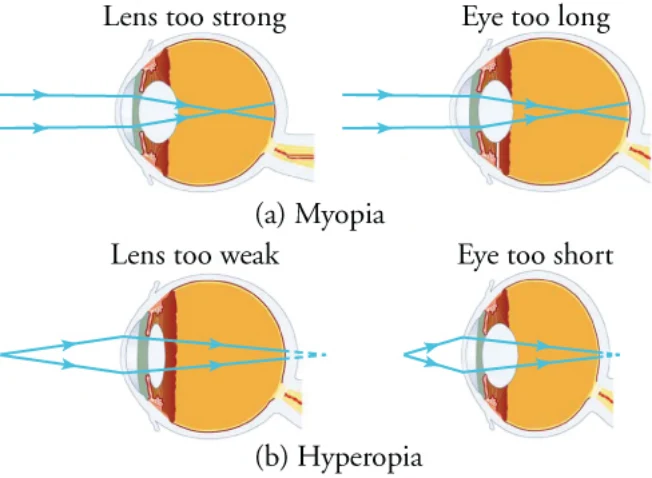
The need for some type of vision correction is very common. Common vision defects are easy to understand, and some are simple to correct. Figure 16.34 illustrates two common vision defects. Nearsightedness, or myopia, is the inability to see distant objects clearly while close objects are in focus. The nearsighted eye overconverges the nearly parallel rays from a distant object, and the rays cross in front of the retina. More divergent rays from a close object are converged on the retina, producing a clear image. Farsightedness, or hyperopia, is the inability to see close objects clearly whereas distant objects may be in focus. A farsighted eye does not converge rays from a close object sufficiently to make the rays meet on the retina. Less divergent rays from a distant object can be converged for a clear image.
何らかの視力の補正が必要なことはとてもよくある。よくある視力の欠陥は簡単に理解でき、単純に補正できるものもある。図16.34によくある二つの視力の欠陥を示す。近視とは、近くの物には焦点が合うのに遠くの物がはっきり見えないことである。近視の目は、遠くの物からのほぼ平行な光線を集めすぎ、光線が網膜の手前で交わってしまう。近くの物からのより広がった光線は網膜上で集まり、はっきりした像を作る。遠視とは、遠くの物には焦点が合うのに近くの物がはっきり見えないことである。遠視の目は、近くの物からの光線を網膜上で交わらせるほど十分には集められない。遠くの物からのあまり広がっていない光線は、はっきりした像を作るように集められる。
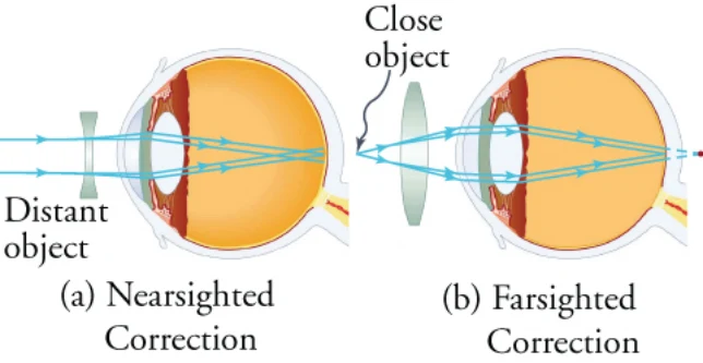
Because the nearsighted eye overconverges light rays, the correction for nearsightedness involves placing a diverging spectacle lens in front of the eye. This lens reduces the power of an eye that has too short a focal length (Figure 16.35(a)). Because the farsighted eye underconverges light rays, the correction for farsightedness is to place a converging spectacle lens in front of the eye. This lens increases the power of an eye that has too long a focal length (Figure 16.35(b)).
近視の目は光線を集めすぎるので、近視の補正には目の前に発散する眼鏡のレンズを置く。このレンズは、焦点距離が短すぎる目の度数を下げる(図16.35(a))。遠視の目は光線を十分に集められないので、遠視の補正には目の前に集束する眼鏡のレンズを置く。このレンズは、焦点距離が長すぎる目の度数を上げる(図16.35(b))。
Calculations Using Lens Equationsレンズの式を使った計算
As promised, there are no new equations to memorize. We can use equations already presented for solving problems involving curved mirrors. Careful analysis allows you to apply these equations to lenses. Here are the equations you need
約束どおり、新しく覚える式はない。曲面鏡の問題を解くのにすでに出てきた式が使える。注意深く分析すれば、これらの式をレンズに応用できる。必要な式は次のとおりである。
where P is power, expressed in reciprocal meters (m–1) rather than diopters (D), and f is focal length, expressed in meters (m). You also need
ここでPは度数で、ジオプター(D)ではなくメートルの逆数(m-1)で表され、fは焦点距離でメートル(m)で表される。次の式も要る。
where, as before, do and di are object distance and image distance, respectively. Remember, this equation is usually more useful if rearranged to solve for one of the variables. For example,
ここでも、doとdiはそれぞれ物までの距離と像までの距離である。この式は、変数の一つについて解く形に変形したほうがふつう役に立つことを覚えておこう。たとえば
The equations for magnification, m, are also the same as for mirrors
倍率mの式も鏡のときと同じである。
where hi and ho are the image height and object height, respectively. Remember, also, that a negative di value indicates a virtual image and a negative hi value indicates an inverted image.
ここでhiとhoはそれぞれ像の高さと物の高さである。また、diの値が負なら虚像、hiの値が負なら倒立した像であることも覚えておこう。
These are the steps to follow when solving a lens problem:
レンズの問題を解くときは次の手順に従う。
Step1. Examine the situation to determine that image formation by a lens is involved. Step2. Determine whether ray tracing, the thin-lens equations, or both should be used. A sketch is very helpful even if ray tracing is not specifically required by the problem. Write useful symbols and values on the sketch. Step3. Identify exactly what needs to be determined in the problem (identify the unknowns). Step4. Make a list of what is given or can be inferred from the problem as stated (identify the knowns). It is helpful to determine whether the situation involves a case 1, 2, or 3 image. Although these are just names for types of images, they have certain characteristics (given in Table 16.3) that can be of great use in solving problems. Step5. If ray tracing is required, use the ray-tracing rules listed earlier in this section. Step6. Most quantitative problems require the use of the thin-lens equations. These equations are solved in the usual manner by substituting knowns and solving for unknowns. Several worked examples were included earlier and
手順1. 場面を調べ、レンズによる像のでき方が関わっていることを確かめる。 手順2. 光線追跡か薄レンズの式か、あるいは両方を使うべきかを判断する。問題が光線追跡を明示的に求めていなくても、図を描くととても役に立つ。図に役立つ記号と値を書き込む。手順3. 問題で何を求めればよいかを正確に見きわめる(未知のものを見きわめる)。 手順4. 問題の記述で与えられているもの、あるいはそこから推し量れるものを一覧にする(分かっているものを見きわめる)。場合1・2・3のどの像が関わるかを判断すると役に立つ。これらは像の型の名にすぎないが、(表16.3にある)特定の性質を持ち、問題を解くのに大いに役立つ。手順5. 光線追跡が必要なら、この節の前に挙げた光線追跡の規則を使う。 手順6. 量的な問題のほとんどは薄レンズの式を使う必要がある。これらの式は、いつものように分かっているものを代入して未知のものについて解く。すでに例題をいくつか
can serve as guides.Step 7. Check whether the answer is reasonable. Does it make sense? If you identified the type of image (case 1, 2, or 3) correctly, you should assess whether your answer is consistent with the type of image, magnification, and so on.
挙げてあり、案内として使える。手順7. 答えが妥当かどうか確かめる。筋が通っているか。像の型(場合1・2・3)を正しく見きわめたなら、答えがその像の型・倍率などと辻褄が合っているかを検討すべきである。
All problems will be solved by one or more of the equations just presented, with ray tracing used only for general analysis of the problem. The steps then simplify to the following:
どの問題も、いま示した式の一つ以上で解ける。光線追跡は問題の全体的な分析にのみ使う。手順はこう単純になる。
1. Identify the unknown.2. Identify the knowns.3. Choose an equation, plug in the knowns, and solve for the unknown.
1. 未知のものを見きわめる。2. 分かっているものを見きわめる。3. 式を選び、分かっているものを入れ、未知のものについて解く。
Here are some worked examples:
いくつか例題を挙げる。
The Power of a Magnifying Glass Strategy虫めがねの度数 方針
The Sun is so far away that its rays are nearly parallel when they reach Earth. The magnifying glass is a convex (or converging) lens, focusing the nearly parallel rays of sunlight. Thus, the focal length of the lens is the distance from the lens to the spot, and its power, in diopters (D), is the inverse of this distance (in reciprocal meters).
太陽はあまりに遠いので、その光線は地球に届くときほぼ平行である。虫めがねは凸レンズ(すなわち集束レンズ)で、ほぼ平行な日光を集める。したがってレンズの焦点距離は、レンズから点までの距離であり、その度数はジオプター(D)で表され、この距離(メートルの逆数)の逆数である。
Solution解答
The focal length of the lens is the distance from the center of the lens to the spot, which we know to be 8.00 cm. Thus,
レンズの焦点距離は、レンズの中心から点までの距離であり、8.00 cmと分かっている。したがって、
To find the power of the lens, we must first convert the focal length to meters; then, we substitute this value into the equation for power.
レンズの度数を求めるには、まず焦点距離をメートルに直し、その値を度数の式に代入せねばならない。
Discussion考察
This result demonstrates a relatively powerful lens. Remember that the power of a lens in diopters should not be confused with the familiar concept of power in watts.
この結果はわりあい強いレンズであることを示す。ジオプターで表したレンズの度数を、なじみのあるワットで表した仕事率と混同しないよう気をつけよう。
Image Formation by a Convex Lens A clear glass light bulb is placed 0.75 m from a convex lens with a 0.50 m focal length, as shown in Figure 16.36. Use ray tracing to get an approximate location for the image. Then, use the mirror/lens equations to calculate (a) the location of the image and (b) its magnification. Verify that ray tracing and the thin-lens and magnification equations produce consistent results.
凸レンズによる像のでき方 図16.36のように、透明なガラスの電球を、焦点距離0.50 mの凸レンズから0.75 mのところに置く。光線追跡で像のおおよその位置を求めよ。次に鏡・レンズの式を使って(a)像の位置と(b)その倍率を計算せよ。光線追跡と、薄レンズの式・倍率の式が辻褄の合う結果を出すことを確かめよ。
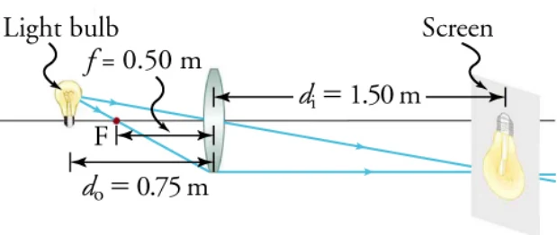
the previous example. Ray tracing predicts the image location and size.
前の例題で論じたように、ポスターボードの上に実像を作る。光線追跡が像の位置と大きさを予測する。
Strategy方針
Because the object is placed farther away from a converging lens than the focal length of the lens, this situation is analogous to the one illustrated in the previous figure of a series of drawings showing a woman standing to the left of a lens. Ray tracing to scale should produce similar results for di. Numerical solutions for di and m can be obtained using the thin-lens and magnification equations, noting that do = 0.75 m and f = 0.50 m.
物が集束レンズの焦点距離より遠くに置かれているので、この場面は、レンズの左に女性が立っている一連の図で示した前の場面と似ている。縮尺を守って光線を追えば、diについて似た結果が出るはずである。do = 0.75 m、f = 0.50 mであることに注意して、薄レンズの式と倍率の式でdiとmの数値を求められる。
Solution解答
The ray tracing to scale in Figure 16.36 shows two rays from a point on the bulb’s filament crossing about 1.50 m on the far side of the lens. Thus, the image distance, di, is about 1.50 m. Similarly, the image height based on ray tracing is greater than the object height by about a factor of two, and the image is inverted. Thus, m is about –2. The minus sign indicates the image is inverted. The lens equation can be rearranged to solve for di from the given information.
図16.36の縮尺を守った光線追跡は、電球のフィラメント上の一点からの二本の光線が、レンズの向こう側およそ1.50 mのところで交わることを示す。したがって像までの距離diはおよそ1.50 mである。同じように、光線追跡にもとづく像の高さは物の高さのおよそ2倍で、像は倒立している。したがってmはおよそ−2である。マイナス符号は像が倒立していることを表す。与えられた情報からdiについて解くように、レンズの式を変形できる。
Now, we use to find m.
次にを使ってmを求める。
Discussion考察
Note that the minus sign causes the magnification to be negative when the image is inverted. Ray tracing and the use of the lens equation produce consistent results. The thin-lens equation gives the most precise results, and is limited only by the accuracy of the given information. Ray tracing is limited by the accuracy with which you draw, but it is highly useful both conceptually and visually.
像が倒立しているとき、マイナス符号によって倍率が負になることに注意しよう。光線追跡とレンズの式の使用は辻褄の合う結果を出す。薄レンズの式が最も精密な結果を与え、その精度は与えられた情報の精度だけで決まる。光線追跡は描く正確さで限界があるが、考え方の上でも目で見る上でもたいへん役に立つ。
Image Formation by a Concave Lens Suppose an object, such as a book page, is held 6.50 cm from a concave lens with a focal length of –10.0 cm. Such a lens could be used in eyeglasses to correct pronounced nearsightedness. What magnification is produced?Strategy
凹レンズによる像のでき方 本のページのような物を、焦点距離−10.0 cmの凹レンズから6.50 cmのところに持つとする。そのようなレンズは、強い近視を補正する眼鏡に使えるだろう。どんな倍率が生じるか。方針
This example is identical to the preceding one, except that the focal length is negative for a concave or diverging lens. The method of solution is therefore the same, but the results are different in important ways.
この例は前のものと同じだが、凹レンズすなわち発散レンズなので焦点距離が負である。したがって解き方は同じだが、結果は大事な点で違ってくる。
Solution解答
Now the magnification equation can be used to find the magnification, m, because both di and do are known. Entering their values gives
diもdoも分かったので、倍率の式で倍率mを求められる。値を入れると
Discussion考察
529A number of results in this example are true of all case 3 images. Magnification is positive (as calculated), meaning the image is upright. The magnification is also less than one, meaning the image is smaller than the object—in this case, a little more than half its size. The image distance is negative, meaning the image is on the same side of the lens as the object. The image is virtual. The image is closer to the lens than the object, because the image distance is smaller in magnitude than the object distance. The location of the image is not obvious when you look through a concave lens. In fact, because the image is smaller than the object, you may think it is farther away; however, the image is closer than the object—a fact that is useful in correcting nearsightedness.
この例の結果のいくつかは、場合3の像すべてに当てはまる。倍率は(計算どおり)正であり、像が正立していることを意味する。倍率はまた1より小さく、像が物より小さい——この場合は半分より少し大きい——ことを意味する。像までの距離は負であり、像が物と同じ側にあることを意味する。像は虚像である。像までの距離の大きさが物までの距離より小さいので、像は物よりレンズに近い。凹レンズを通して見るとき、像の位置は明らかではない。実のところ、像が物より小さいので、より遠くにあると思うかもしれない。しかし像は物より近い——この事実が近視の補正に役立つ。
The Lens Equation and Problem Solving The video shows calculations for both concave and convex lenses. It also explains real versus virtual images, erect versus inverted images, and the significance of negative and positive signs for the involved variables.
レンズの式と問題の解き方 この動画は凹レンズと凸レンズの両方の計算を示す。実像と虚像、正立の像と倒立の像、そして関わる変数の負と正の符号の意味も説明する。
Access multimedia content (http://openstax.org/books/physics/pages/16-3-lenses) Watch Physics: Thin Lens Equation and Problem Solving This video gives examples using the thin lens equation. Access multimedia content (http://openstax.org/books/physics/pages/16-3-lenses) If a lens has a magnification of , how does the image compare with the object in height and orientation?
マルチメディア教材はこちら(http://openstax.org/books/physics/pages/16-3-lenses)物理を見る:薄レンズの式と問題の解き方 この動画は薄レンズの式を使った例を示す。マルチメディア教材はこちら(http://openstax.org/books/physics/pages/16-3-lenses) あるレンズの倍率がのとき、像は物とくらべて高さと向きがどうなっているか。
a. The image is erect and is half as tall as the object.b. The image is erect and twice as tall as the object.
a. 像は正立で、物の半分の高さである。b. 像は正立で、物の2倍の高さである。
c. The image is inverted and is half as tall as the object.d. The image is inverted and is twice as tall as the object.
c. 像は倒立で、物の半分の高さである。d. 像は倒立で、物の2倍の高さである。
Practice Problems練習問題
11A lens has a focal length of . What is the power of the lens?a. The power of the lens is .b. The power of the lens is .c. The power of the lens is .d. The power of the lens is .
11あるレンズの焦点距離がである。このレンズの度数はいくらか。a. このレンズの度数はである。b. このレンズの度数はである。c. このレンズの度数はである。d. このレンズの度数はである。
12If a lens produces a 5.00 -cm tall image of an 8.00 -cm -high object when placed 10.0 cm from the lens, what is the apparent image distance? Construct a ray diagram using paper, a pencil, and a ruler to confirm your calculation.
12レンズから10.0 cmのところに置かれた高さ8.00 cmの物について、レンズが高さ5.00 cmの像を作るとき、見かけの像までの距離はいくらか。紙と鉛筆と定規で光線図を描いて計算を確かめよ。
a. −3.12 cmb. −6.25 cmc. 3.12 cmd. 6.25 cm
a. −3.12 cmb. −6.25 cmc. 3.12 cmd. 6.25 cm
Check Your Understanding理解の確認
13A lens has a magnification that is negative. What is the orientation of the image?a. Negative magnification means the image is erect and real.b. Negative magnification means the image is erect and virtual.
13あるレンズの倍率が負である。像の向きはどうなっているか。a. 負の倍率は、像が正立の実像であることを意味する。b. 負の倍率は、像が正立の虚像であることを意味する。
c. Negative magnification means the image is inverted and virtual.d. Negative magnification means the image is inverted and real.
c. 負の倍率は、像が倒立の虚像であることを意味する。d. 負の倍率は、像が倒立の実像であることを意味する。
14Which part of the eye controls the amount of light that enters?a. the pupilb. the iris
14入ってくる光の量を制御しているのは目のどの部分か。a. 瞳孔b. 虹彩
c. the cornead. the retina
c. 角膜d. 網膜
15An object is placed between the focal point and a convex lens. Describe the image that is formed in terms of its orientation and whether the image is real or virtual.
15焦点と凸レンズの間に物を置く。できる像を、その向きと、実像か虚像かの言葉で述べよ。
a. The image is real and erect.
a. 像は正立の実像である。
b. The image is real and inverted.
b. 像は倒立の実像である。
c. The image is virtual and erect.d. The image is virtual and inverted.
c. 像は正立の虚像である。d. 像は倒立の虚像である。
16A farsighted person buys a pair of glasses to correct her farsightedness. Describe the main symptom of farsightedness and the type of lens that corrects it.
16遠視の人が遠視を補正する眼鏡を買う。遠視のおもな症状と、それを補正するレンズの種類を述べよ。
a. Farsighted people cannot focus on objects that are far away, but they can see nearby objects easily. A convex lens is used to correct this.b. Farsighted people cannot focus on objects that are close up, but they can see far-off objects easily. A concave lens is used to correct this.c. Farsighted people cannot focus on objects that are close up, but they can see distant objects easily. A convex lens is used to correct this.d. Farsighted people cannot focus on objects that are either close up or far away. A concave lens is used to correct this.
a. 遠視の人は遠くの物に焦点を合わせられないが、近くの物は簡単に見える。これを補正するには凸レンズを使う。b. 遠視の人は近くの物に焦点を合わせられないが、遠くの物は簡単に見える。これを補正するには凹レンズを使う。c. 遠視の人は近くの物に焦点を合わせられないが、遠くの物は簡単に見える。これを補正するには凸レンズを使う。d. 遠視の人は近くの物にも遠くの物にも焦点を合わせられない。これを補正するには凹レンズを使う。