第20章磁性Magnetism原書 p.669–710
20.3 Electromagnetic Induction20.3 電磁誘導
SECTION LEARNING OBJECTIVES By the end of this section, you will be able to do the following:
この節の学習目標 この節を終えると、次のことができるようになる。
• Explain how a changing magnetic field produces a current in a wire• Calculate induced electromotive force and current
・変わる磁場が導線に電流をどう生むかを説明する・誘導起電力と誘導電流を計算する
Section Key Termsこの節の重要語
emfinductionmagnetic flux
起電力誘導磁束
Changing Magnetic Fields変わる磁場
In the preceding section, we learned that a current creates a magnetic field. If nature is symmetrical, then perhaps a magnetic field can create a current. In 1831, some 12 years after the discovery that an electric current generates a magnetic field, English scientist Michael Faraday (1791–1862) and American scientist Joseph Henry (1797–1878) independently demonstrated that magnetic fields can produce currents. The basic process of generating currents with magnetic fields is called induction; this process is also called magnetic induction to distinguish it from charging by induction, which uses the electrostatic Coulomb force.
前の節で、電流が磁場を作ることを学んだ。自然が対称なら、磁場も電流を作れるかもしれない。1831年、電流が磁場を作るという発見から12年ほどして、イギリスの科学者マイケル・ファラデー(1791–1862)とアメリカの科学者ジョセフ・ヘンリー(1797–1878)が、それぞれ独立に磁場が電流を作れることを示した。磁場で電流を作る基本の過程を誘導という。静電気のクーロン力を使う誘導による帯電と区別するために、磁気誘導とも呼ばれる。
When Faraday discovered what is now called Faraday’s law of induction, Queen Victoria asked him what possible use was electricity. “Madam,” he replied, “What good is a baby?” Today, currents induced by magnetic fields are essential to our technological society. The electric generator—found in everything from automobiles to bicycles to nuclear power plants—uses magnetism to generate electric current. Other devices that use magnetism to induce currents include pickup coils in electric guitars, transformers of every size, certain microphones, airport security gates, and damping mechanisms on sensitive chemical balances.
ファラデーがいまファラデーの誘導の法則と呼ばれるものを見つけたとき、ビクトリア女王は電気が何の役に立つのかと尋ねた。「陛下」と彼は答えた。「赤ん坊が何の役に立ちますか。」今日、磁場が誘導する電流は私たちの技術の社会に欠かせない。自動車から自転車、原子力発電所まで、あらゆるものに見られる発電機は、磁気を使って電流を作る。磁気を使って電流を誘導する他の装置には、エレキギターのピックアップコイル、あらゆる大きさの変圧器、ある種のマイクロフォン、空港の保安ゲート、感度のよい化学天びんの制動の仕組みがある。
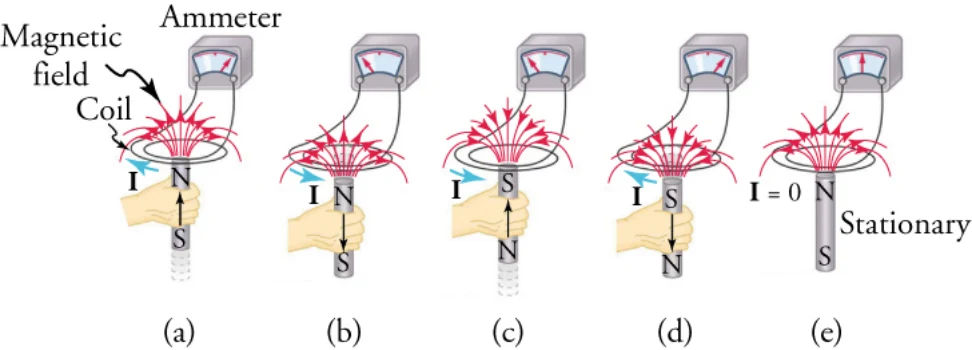
One experiment Faraday did to demonstrate magnetic induction was to move a bar magnet through a wire coil and measure the resulting electric current through the wire. A schematic of this experiment is shown in Figure 20.33. He found that current is induced only when the magnet moves with respect to the coil. When the magnet is motionless with respect to the coil, no current is induced in the coil, as in Figure 20.33. In addition, moving the magnet in the opposite direction (compare Figure 20.33 with Figure 20.33) or reversing the poles of the magnet (compare Figure 20.33 with Figure 20.33) results in a current in the opposite direction.
ファラデーが磁気誘導を示すために行った実験の一つが、棒磁石を導線のコイルの中を通して動かし、それによって導線に流れる電流を測ることだった。この実験の模式図を図20.33に示す。彼は、磁石がコイルに対して動くときにだけ電流が誘導されることを見いだした。磁石がコイルに対して静止していれば、図20.33のようにコイルに電流は誘導されない。さらに、磁石を逆向きに動かすか(図20.33と図20.33を比べよ)、磁石の極を逆にすると(図20.33と図20.33を比べよ)、逆向きの電流が流れる。
VIRTUAL PHYSICSシミュレーションFaraday’s Lawファラデーの法則
Access multimedia content (http://openstax.org/books/physics/pages/20-3-electromagnetic-induction) Try this simulation to see how moving a magnet creates a current in a circuit. A light bulb lights up to show when current is flowing, and a voltmeter shows the voltage drop across the light bulb. Try moving the magnet through a four-turn coil and through a two-turn coil. For the same magnet speed, which coil produces a higher voltage?
マルチメディア教材はこちら(http://openstax.org/books/physics/pages/20-3-electromagnetic-induction) このシミュレーションを試して、磁石を動かすと回路に電流ができる様子を見よう。電流が流れているときに電球が点り、電圧計が電球にかかる電圧の降下を示す。磁石を四巻きのコイルと二巻きのコイルの中を通して動かしてみよう。同じ磁石の速さで、どちらのコイルがより高い電圧を生むか。
With the north pole to the left and moving the magnet from right to left, a positive voltage is produced as the magnet enters the coil. What sign voltage will be produced if the experiment is repeated with the south pole to the left?
N極を左にして磁石を右から左へ動かすと、磁石がコイルに入るときに正の電圧が生じる。S極を左にして同じ実験を繰り返したら、どんな符号の電圧が生じるか。
a. The sign of voltage will change because the direction of current flow will change by moving south pole of the magnet to the left.b. The sign of voltage will remain same because the direction of current flow will not change by moving south pole of the magnet to the left.c. The sign of voltage will change because the magnitude of current flow will change by moving south pole of the magnet to the left.d. The sign of voltage will remain same because the magnitude of current flow will not change by moving south pole of the magnet to the left.
a. 磁石のS極を左にして動かすと電流の流れる向きが変わるので、電圧の符号は変わる。b. 磁石のS極を左にして動かしても電流の流れる向きは変わらないので、電圧の符号は変わらない。c. 磁石のS極を左にして動かすと電流の大きさが変わるので、電圧の符号は変わる。d. 磁石のS極を左にして動かしても電流の大きさは変わらないので、電圧の符号は変わらない。
Induced Electromotive Force誘導起電力
If a current is induced in the coil, Faraday reasoned that there must be what he called an electromotive force pushing the charges through the coil. This interpretation turned out to be incorrect; instead, the external source doing the work of moving the magnet adds energy to the charges in the coil. The energy added per unit charge has units of volts, so the electromotive force is actually a potential. Unfortunately, the name electromotive force stuck and with it the potential for confusing it with a real force. For this reason, we avoid the term electromotive force and just use the abbreviation emf, which has the mathematical symbol The emf may be defined as the rate at which energy is drawn from a source per unit current flowing through a circuit. Thus, emf is the energy per unit charge added by a source, which contrasts with voltage, which is the energy per unit charge released as the charges flow through a circuit.
コイルに電流が誘導されるなら、コイルに電荷を押し流す「起電力」と彼が呼んだものがあるはずだ、とファラデーは考えた。この解釈は正しくないことが分かった。実際には、磁石を動かす仕事をする外部の源がコイルの電荷にエネルギーを加えているのである。単位電荷あたりに加えられるエネルギーはボルトの単位を持つので、起電力は実は電位である。あいにく「起電力」という名が定着し、それとともに本当の力と混同する余地も残った。このため私たちは起電力(electromotive force)という語を避け、数学の記号を持つ略号emfだけを使う。起電力は、回路を流れる単位電流あたりに源から引き出されるエネルギーの速さと定義できる。したがって起電力は源が加える単位電荷あたりのエネルギーであり、電荷が回路を流れるときに放される単位電荷あたりのエネルギーである電圧とは対をなす。
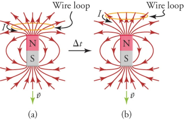
To understand why an emf is generated in a coil due to a moving magnet, consider Figure 20.34, which shows a bar magnet moving downward with respect to a wire loop. Initially, seven magnetic field lines are going through the loop (see left-hand image). Because the magnet is moving away from the coil, only five magnetic field lines are going through the loop after a short time (see right-hand image). Thus, when a change occurs in the number of magnetic field lines going through the area defined by the wire loop, an emf is induced in the wire loop. Experiments such as this show that the induced emf is proportional to the rate of change of the magnetic field. Mathematically, we express this as
動く磁石によってコイルに起電力が生じる理由を理解するために、導線の輪に対して下へ動く棒磁石を示す図20.34を考えよう。はじめ7本の磁力線が輪を通っている(左の図を見よ)。磁石はコイルから遠ざかっているので、短い時間のあと5本の磁力線しか輪を通らない(右の図を見よ)。したがって、導線の輪が囲む面積を通る磁力線の数に変化が起こると、導線の輪に起電力が誘導される。このような実験から、誘導起電力は磁場の変化の速さに比例することが分かる。数式で表せば
where is the change in the magnitude in the magnetic field during time and A is the area of the loop.
となる。ここでは時間のあいだの磁場の大きさの変化、Aは輪の面積である。
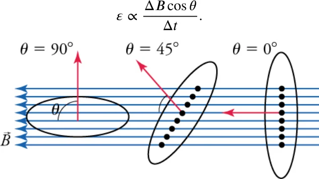
Note that magnetic field lines that lie in the plane of the wire loop do not actually pass through the loop, as shown by the left-most loop in Figure 20.35. In this figure, the arrow coming out of the loop is a vector whose magnitude is the area of the loop and whose direction is perpendicular to the plane of the loop. In Figure 20.35, as the loop is rotated from to the contribution of the magnetic field lines to the emf increases. Thus, what is important in generating an emf in the wire loop is the component of the magnetic field that is perpendicular to the plane of the loop, which is
図20.35の一番左の輪が示すように、導線の輪の面内にある磁力線は実際には輪を通らないことに注意しよう。この図で輪から出ている矢印は、大きさが輪の面積で、向きが輪の面に垂直なベクトルである。図20.35で、輪がからへ回されるにつれ、磁力線の起電力への寄与は増える。したがって、導線の輪に起電力を生むのに大事なのは、輪の面に垂直な磁場の成分である。
This is analogous to a sail in the wind. Think of the conducting loop as the sail and the magnetic field as the wind. To maximize the force of the wind on the sail, the sail is oriented so that its surface vector points in the same direction as the winds, as in the right-most loop in Figure 20.35. When the sail is aligned so that its surface vector is perpendicular to the wind, as in the left-most loop in Figure 20.35, then the wind exerts no force on the sail.
これは風を受ける帆と似ている。導体の輪を帆、磁場を風と考えよう。帆にはたらく風の力を最大にするには、図20.35の一番右の輪のように、帆の面のベクトルが風と同じ向きを指すようにする。図20.35の一番左の輪のように、帆の面のベクトルが風に垂直に揃っていれば、風は帆に力を及ぼさない。
Thus, taking into account the angle of the magnetic field with respect to the area, the proportionality becomes
したがって、面積に対する磁場の角度を考えに入れると、比例関係は
Another way to reduce the number of magnetic field lines that go through the conducting loop in Figure 20.35 is not to move the magnet but to make the loop smaller. Experiments show that changing the area of a conducting loop in a stable magnetic field induces an emf in the loop. Thus, the emf produced in a conducting loop is proportional to the rate of change of the product of the perpendicular magnetic field and the loop area
図20.35で導体の輪を通る磁力線の数を減らすもう一つのやり方は、磁石を動かすのではなく輪を小さくすることである。実験によれば、変わらない磁場の中で導体の輪の面積を変えると、輪に起電力が誘導される。したがって、導体の輪に生じる起電力は、垂直な磁場と輪の面積の積の変化の速さに比例する。
where is the perpendicular magnetic field and A is the area of the loop. The product is very important. It is proportional to the number of magnetic field lines that pass perpendicularly through a surface of area A. Going back to our sail analogy, it would be proportional to the force of the wind on the sail. It is called the magnetic flux and is represented by .
ここでは垂直な磁場、Aは輪の面積である。積はとても重要である。それは、面積Aの面を垂直に通り抜ける磁力線の数に比例する。帆の類比に戻れば、それは帆にはたらく風の力に比例するだろう。これを磁束といい、で表す。
The unit of magnetic flux is the weber (Wb), which is magnetic field per unit area, or T/m2. The weber is also a volt second (Vs).
磁束の単位はウェーバ(Wb)で、単位面積あたりの磁場、すなわちT/m2である。ウェーバはボルト秒(Vs)でもある。
The induced emf is in fact proportional to the rate of change of the magnetic flux through a conducting loop.
誘導起電力は、実のところ導体の輪を通る磁束の変化の速さに比例する。
Finally, for a coil made from N loops, the emf is N times stronger than for a single loop. Thus, the emf induced by a changing magnetic field in a coil of N loops is
最後に、N巻きのコイルでは起電力は一巻きのN倍強い。したがって、N巻きのコイルで変わる磁場が誘導する起電力は
The last question to answer before we can change the proportionality into an equation is “In what direction does the current flow?” The Russian scientist Heinrich Lenz (1804–1865) explained that the current flows in the direction that creates a magnetic field that tries to keep the flux constant in the loop. For example, consider again Figure 20.34. The motion of the bar magnet causes the number of upward-pointing magnetic field lines that go through the loop to decrease. Therefore, an emf is generated in the loop that drives a current in the direction that creates more upward-pointing magnetic field lines. By using the right-hand rule, we see that this current must flow in the direction shown in the figure. To express the fact that the induced emf acts to counter the change in the magnetic flux through a wire loop, a minus sign is introduced into the proportionality , which gives Faraday’s law of induction.
比例関係を等式に変える前に答えるべき最後の問いは「電流はどちら向きに流れるか」である。ロシアの科学者ハインリヒ・レンツ(1804–1865)は、電流は輪の中の磁束を一定に保とうとする磁場を作る向きに流れると説明した。たとえばもう一度図20.34を考えよう。棒磁石の動きによって、輪を通る上向きの磁力線の数が減る。したがって、上向きの磁力線をより多く作る向きに電流を流す起電力が輪に生じる。右手の法則を使えば、この電流は図に示す向きに流れねばならないと分かる。誘導起電力が導線の輪を通る磁束の変化に逆らってはたらくという事実を表すために、比例関係にマイナス符号が導かれ、それがファラデーの誘導の法則を与える。
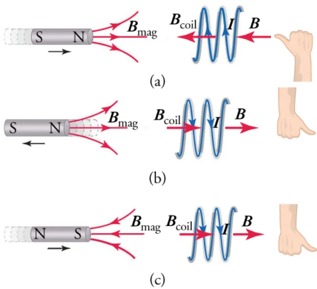
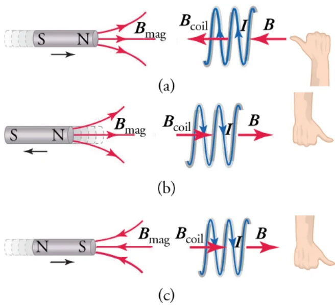
Lenz’s law is very important. To better understand it, consider Figure 20.36, which shows a magnet moving with respect to a wire coil and the direction of the resulting current in the coil. In the top row, the north pole of the magnet approaches the coil, so the magnetic field lines from the magnet point toward the coil. Thus, the magnetic field pointing to the right increases in the coil. According to Lenz’s law, the emf produced in the coil will drive a current in the direction that creates a magnetic field inside the coil pointing to the left. This will counter the increase in magnetic flux pointing to the right. To see which way the current must flow,
レンツの法則はとても重要である。よりよく理解するために、導線のコイルに対して動く磁石と、その結果コイルに流れる電流の向きを示す図20.36を考えよう。上の段では磁石のN極がコイルに近づくので、磁石からの磁力線はコイルのほうを指す。したがって、右を指す磁場がコイルの中で増える。レンツの法則によれば、コイルに生じる起電力は、コイルの内側に左を指す磁場を作る向きに電流を流す。これが右を指す磁束の増加を打ち消す。電流がどちら向きに流れねばならないかを見るには、
point your right thumb in the desired direction of the magnetic field and the current will flow in the direction indicated by curling your right fingers. This is shown by the image of the right hand in the top row of Figure 20.36. Thus, the current must flow in the direction shown in Figure 4(a).
望みの磁場の向きに右手の親指を向ければ、電流は右手の指を丸めた向きに流れる。これを図20.36の上の段の右手の図が示している。したがって電流は図4(a)に示す向きに流れねばならない。
In Figure 4(b), the direction in which the magnet moves is reversed. In the coil, the right-pointing magnetic field
図4(b)では磁石が動く向きが逆になっている。コイルの中で、動く磁石による右を指す磁場は
due to the moving magnet decreases. Lenz’s law says that, to counter this decrease, the emf will drive a current that creates an additional right-pointing magnetic field in the coil. Again, point your right thumb in the desired direction of the magnetic field, and the current will flow in the direction indicate by curling your right fingers (Figure 4(b)).
減る。レンツの法則は、この減少を打ち消すために、起電力がコイルにさらに右を指す磁場を作る電流を流すと言う。ここでも右手の親指を望みの磁場の向きに向ければ、電流は右手の指を丸めた向きに流れる(図4(b))。
Finally, in Figure 4(c), the magnet is reversed so that the south pole is nearest the coil. Now the magnetic field
最後に図4(c)では磁石が逆にされ、S極がコイルに最も近い。いまや磁場は
points toward the magnet instead of toward the coil. As the magnet approaches the coil, it causes the left-
コイルのほうでなく磁石のほうを指す。磁石がコイルに近づくにつれ、コイルの中の
pointing magnetic field in the coil to increase. Lenz’s law tells us that the emf induced in the coil will drive a current in the direction that creates a magnetic field pointing to the right. This will counter the increasing magnetic flux pointing to the left due to the magnet. Using the right-hand rule again, as indicated in the figure, shows that the current must flow in the direction shown in Figure 4(c).
左を指す磁場が増える。レンツの法則は、コイルに誘導される起電力が、右を指す磁場を作る向きに電流を流すと教える。これが磁石による左を指す磁束の増加を打ち消す。図に示すようにまた右手の法則を使えば、電流は図4(c)に示す向きに流れねばならないと分かる。
VIRTUAL PHYSICSシミュレーションFaraday’s Electromagnetic Labファラデーの電磁気の実験室
Access multimedia content (http://openstax.org/books/physics/pages/20-3-electromagnetic-induction) This simulation proposes several activities. For now, click on the tab Pickup Coil, which presents a bar magnet that you can move through a coil. As you do so, you can see the electrons move in the coil and a light bulb will light up or a voltmeter will indicate the voltage across a resistor. Note that the voltmeter allows you to see the sign of the voltage as you move the magnet about. You can also leave the bar magnet at rest and move the coil, although it is more difficult to observe the results.
マルチメディア教材はこちら(http://openstax.org/books/physics/pages/20-3-electromagnetic-induction) このシミュレーションはいくつもの活動を用意している。ここでは「Pickup Coil」タブを押そう。コイルの中を通して動かせる棒磁石が現れる。動かすと、コイルの中で電子が動くのが見え、電球が点るか電圧計が抵抗にかかる電圧を示す。電圧計を使えば、磁石を動かすときの電圧の符号が見える。棒磁石を止めたままコイルを動かすこともできるが、結果を観察するのはより難しい。
PhET Explorations: Faraday's Electromagnetic Lab Play with a bar magnet and coils to learn about Faraday's law. Move a bar magnet near one or two coils to make a light bulb glow. View the magnetic field lines. A meter shows the direction and magnitude of the current. View the magnetic field lines or use a meter to show the direction and magnitude of the current. You can also play with electromagnets, generators and transformers!Access multimedia content (http://openstax.org/books/physics/pages/20-3-electromagnetic-induction) Orient the bar magnet with the north pole facing to the right and place the pickup coil to the right of the bar magnet. Now move the bar magnet toward the coil and observe in which way the electrons move. This is the same situation as depicted below. Does the current in the simulation flow in the same direction as shown
PhET探究:ファラデーの電磁気の実験室 棒磁石とコイルで遊んでファラデーの法則を学ぼう。棒磁石を一つか二つのコイルの近くで動かして電球を光らせよう。磁力線を見よう。計器が電流の向きと大きさを示す。磁力線を見るか、計器で電流の向きと大きさを示そう。電磁石・発電機・変圧器でも遊べる。マルチメディア教材はこちら(http://openstax.org/books/physics/pages/20-3-electromagnetic-induction) 棒磁石のN極を右に向け、ピックアップコイルを棒磁石の右に置く。次に棒磁石をコイルのほうへ動かし、電子がどちら向きに動くかを観察しよう。これは下に描いた場面と同じである。シミュレーションの電流は下に示すのと
below? Explain why or why not.
同じ向きに流れるか。なぜそうか、あるいはなぜそうでないかを説明せよ。
a. Yes, the current in the simulation flows as shown because the direction of current is opposite to the direction of flow of electrons.b. No, current in the simulation flows in the opposite direction because the direction of current is same to the direction of flow of electrons.
a. はい。電流の向きは電子の流れる向きと逆なので、シミュレーションの電流は図のように流れる。b. いいえ。電流の向きは電子の流れる向きと同じなので、シミュレーションの電流は逆向きに流れる。
Induced Current in a Wire This video explains how a current can be induced in a straight wire by moving it through a magnetic field. The lecturer uses the cross product, which a type of vector multiplication. Don’t worry if you are not familiar with this, it basically combines the right-hand rule for determining the force on the charges in the wire with the equation
導線に誘導される電流 この動画は、まっすぐな導線を磁場の中で動かして電流を誘導できることを説明する。講師はベクトルのかけ算の一種である外積を使う。これになじみがなくても心配はいらない。要するに、導線の中の電荷にはたらく力を決める右手の法則を、式
Induced current in a wire | Physics | Khan Academy (https://www.openstax.org/l/induced-current)
と組み合わせたものである。 導線に誘導される電流|物理|カーンアカデミー(https://www.openstax.org/l/induced-current)
GRASP CHECK What emf is produced across a straight wire 0.50 m long moving at a velocity of (1.5 m/s) through a uniform magnetic field (0.30 T)ẑ? The wire lies in the ŷ-direction. Also, which end of the wire is at the higher potential—let the lower end of the wire be at y = 0 and the upper end at y = 0.5 m)?
理解の確認 一様な磁場(0.30 T)ẑの中を速度(1.5 m/s)で動く長さ0.50 mのまっすぐな導線には、どんな起電力が生じるか。導線はŷ方向にある。また、導線のどちらの端の電位が高いか(導線の下端をy = 0、上端をy = 0.5 mとする)。
a. 0.15 V and the lower end of the wire will be at higher potentialb. 0.15 V and the upper end of the wire will be at higher potential
a. 0.15 Vで、導線の下端の電位が高いb. 0.15 Vで、導線の上端の電位が高い
c. 0.075 V and the lower end of the wire will be at higher potentiald. 0.075 V and the upper end of the wire will be at higher potential
c. 0.075 Vで、導線の下端の電位が高いd. 0.075 Vで、導線の上端の電位が高い
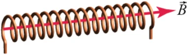
EMF Induced in Conducing Coil by Moving Magnet Imagine a magnetic field goes through a coil in the direction indicated in Figure 20.37. The coil diameter is 2.0 cm. If the magnetic field goes from 0.020 to 0.010 T in 34 s, what is the direction and magnitude of the induced current? Assume the coil has a resistance of 0.1
動く磁石が導体のコイルに誘導する起電力 図20.37に示す向きに磁場がコイルを通っているとする。コイルの直径は2.0 cmである。磁場が34 sで0.020 Tから0.010 Tへ変わるとき、誘導される電流の向きと大きさはいくらか。コイルの抵抗は0.1 とする。
Strategy方針
Use the equation to find the induced emf in the coil, where . Counting the number of loops in the solenoid, we find it has 16 loops, so Use the equation to calculate the magnetic flux
式を使ってコイルに誘導される起電力を求める。ここでである。ソレノイドの巻き数を数えると16巻きなので、である。式を使って磁束を計算する。
where d is the diameter of the solenoid and we have used Because the area of the solenoid does not vary, the change in the magnetic of the flux through the solenoid is
ここでdはソレノイドの直径で、を使った。ソレノイドの面積は変わらないので、ソレノイドを通る磁束の大きさの変化は
Once we find the emf, we can use Ohm’s law, to find the current.
となる。起電力が分かれば、オームの法則で電流を求められる。
Finally, Lenz’s law tells us that the current should produce a magnetic field that acts to oppose the decrease in the applied magnetic field. Thus, the current should produce a magnetic field to the right.
最後に、レンツの法則は、電流はかけられた磁場の減少に逆らう磁場を作るはずだと教える。したがって電流は右向きの磁場を作るはずである。
Solution解答
Combining equations and gives
式とを組み合わせると
Solving Ohm’s law for the current and using this result gives
オームの法則を電流について解き、この結果を使うと
Lenz’s law tells us that the current must produce a magnetic field to the right. Thus, we point our right thumb to the right and curl our right fingers around the solenoid. The current must flow in the direction in which our fingers are pointing, so it enters at the left end of the solenoid and exits at the right end.
レンツの法則は、電流が右向きの磁場を作らねばならないと教える。したがって右手の親指を右に向け、右手の指をソレノイドのまわりに丸める。電流は指の指す向きに流れねばならないので、ソレノイドの左端から入り右端から出る。
Discussion考察
Let’s see if the minus sign makes sense in Faraday’s law of induction. Define the direction of the magnetic field to be the positive direction. This means the change in the magnetic field is negative, as we found above. The minus sign in Faraday’s law of induction negates the negative change in the magnetic field, leaving us with a positive current. Therefore, the current must flow in the direction of the magnetic field, which is what we found.
ファラデーの誘導の法則のマイナス符号が筋が通っているか見てみよう。磁場の向きを正の向きと定める。これは、上で求めたとおり磁場の変化が負だということである。ファラデーの誘導の法則のマイナス符号が磁場の負の変化を打ち消し、正の電流が残る。したがって電流は磁場の向きに流れねばならず、それが求めたとおりである。
Now try defining the positive direction to be the direction opposite that of the magnetic field, that is positive is to the left in Figure 20.37. In this case, you will find a negative current. But since the positive direction is to the left, a negative current must flow to the right, which again agrees with what we found by using Lenz’s law.
こんどは、正の向きを磁場と逆の向き、すなわち図20.37で左向きと定めてみよう。この場合、電流は負になる。しかし正の向きが左なので、負の電流は右へ流れねばならず、これもまたレンツの法則で求めたことと合う。
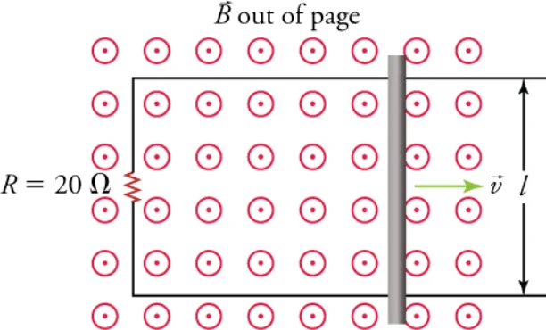
Magnetic Induction due to Changing Circuit Size The circuit shown in Figure 20.38 consists of a U-shaped wire with a resistor and with the ends connected by a sliding conducting rod. The magnetic field filling the area enclosed by the circuit is constant at 0.01 T. If the rod is pulled to the right at speed what current is induced in the circuit and in what direction does the current flow?
回路の大きさの変化による磁気誘導 図20.38の回路は、抵抗のついたU字形の導線と、その端をつなぐ滑る導体の棒からなる。回路が囲む面積を満たす磁場は0.01 Tで一定である。棒を速さで右へ引くとき、回路にはどんな電流がどちら向きに誘導されるか。
Strategy方針
We again use Faraday’s law of induction, although this time the magnetic field is constant and the area enclosed by the circuit changes. The circuit contains a single loop, so The rate of change of the area is Thus the rate of change of the magnetic flux is
ここでもファラデーの誘導の法則を使うが、今回は磁場が一定で、回路が囲む面積が変わる。回路は一つの輪を含むのでである。面積の変化の速さはである。したがって磁束の変化の速さは
where we have used the fact that the angle between the area vector and the magnetic field is 0°. Once we know the emf, we can find the current by using Ohm’s law. To find the direction of the current, we apply Lenz’s law.
となる。ここで、面積のベクトルと磁場の間の角度が0°であることを使った。起電力が分かれば、オームの法則で電流を求められる。電流の向きを求めるにはレンツの法則を当てはめる。
Solution解答
Faraday’s law of induction gives
ファラデーの誘導の法則から
Solving Ohm’s law for the current and using the previous result for emf gives
オームの法則を電流について解き、先の起電力の結果を使うと
As the rod slides to the right, the magnetic flux passing through the circuit increases. Lenz’s law tells us that the current induced will create a magnetic field that will counter this increase. Thus, the magnetic field created by the induced current must be into the page. Curling your right-hand fingers around the loop in the clockwise direction makes your right thumb point into the page, which is the desired direction of the magnetic field. Thus, the current must flow in the clockwise direction around the circuit.
棒が右へ滑るにつれ、回路を通る磁束が増える。レンツの法則は、誘導される電流がこの増加に逆らう磁場を作ると教える。したがって誘導電流が作る磁場は紙面の奥を向かねばならない。右手の指を輪のまわりに時計回りに丸めると右手の親指が紙面の奥を指し、それが望みの磁場の向きである。したがって電流は回路のまわりを時計回りに流れねばならない。
Discussion考察
Is energy conserved in this circuit? An external agent must pull on the rod with sufficient force to just balance the force on a current-carrying wire in a magnetic field—recall that The rate at which this force does work on the rod should be balanced by the rate at which the circuit dissipates power. Using the force required to pull the wire at a constant speed v is
この回路でエネルギーは保存されるか。外部の作用者は、磁場の中で電流の流れる導線にはたらく力とちょうど釣り合うだけの力で棒を引かねばならない——を思い出そう。この力が棒に仕事をする速さは、回路が電力を消散させる速さと釣り合うはずである。を使うと、一定の速さvで導線を引くのに必要な力は
where we used the fact that the angle between the current and the magnetic field is Inserting our expression above for the current into this equation gives
となる。ここで、電流と磁場の間の角度がであることを使った。上で求めた電流の式をこれに入れると
The power contributed by the agent pulling the rod is
棒を引く作用者が与える仕事率は
The power dissipated by the circuit is
回路が消散させる電力は
We thus see that which means that power is conserved in the system consisting of the circuit and the agent that pulls the rod. Thus, energy is conserved in this system.
したがってであり、これは回路と棒を引く作用者からなる系で仕事率が保存されることを意味する。したがってこの系ではエネルギーが保存される。
Practice Problems練習問題
11The magnetic flux through a single wire loop changes from 3.5 Wb to 1.5 Wb in 2.0 s. What emf is induced in the loop?
11一巻きの導線の輪を通る磁束が2.0 sで3.5 Wbから1.5 Wbへ変わる。この輪に誘導される起電力はいくらか。
a. –2.0 Vb. –1.0 Vc. +1.0 Vd. +2.0 V
a. −2.0 Vb. −1.0 Vc. +1.0 Vd. +2.0 V
12What is the emf for a 10-turn coil through which the flux changes at 10 Wb/s?a. –100 Vb. –10 V
12磁束が10 Wb/sで変わる10巻きのコイルの起電力はいくらか。a. −100 Vb. −10 V
c. +10 Vd. +100 V
c. +10 Vd. +100 V
Check Your Understanding理解の確認
13Given a bar magnet, how can you induce an electric current in a wire loop?a. An electric current is induced if a bar magnet is placed near the wire loop.b. An electric current is induced if a wire loop is wound around the bar magnet.
13棒磁石があるとき、導線の輪にどうすれば電流を誘導できるか。a. 棒磁石を導線の輪の近くに置けば電流が誘導される。b. 導線の輪を棒磁石に巻きつければ電流が誘導される。
c. An electric current is induced if a bar magnet is moved through the wire loop.d. An electric current is induced if a bar magnet is placed in contact with the wire loop.
c. 棒磁石を導線の輪の中を通して動かせば電流が誘導される。d. 棒磁石を導線の輪に触れさせれば電流が誘導される。
14What factors can cause an induced current in a wire loop through which a magnetic field passes?a. Induced current can be created by changing the size of the wire loop only.b. Induced current can be created by changing the orientation of the wire loop only.
14磁場が通り抜ける導線の輪に電流を誘導しうる要因はどれか。a. 誘導電流は導線の輪の大きさを変えることでのみ作れる。b. 誘導電流は導線の輪の向きを変えることでのみ作れる。
c. Induced current can be created by changing the strength of the magnetic field only.d. Induced current can be created by changing the strength of the magnetic field, changing the size of the wire loop, or changing the orientation of the wire loop.
c. 誘導電流は磁場の強さを変えることでのみ作れる。d. 誘導電流は、磁場の強さを変える、導線の輪の大きさを変える、あるいは導線の輪の向きを変えることで作れる。