第20章磁性Magnetism原書 p.669–710
20.2 Motors, Generators, and Transformers20.2 電動機、発電機、変圧器
SECTION LEARNING OBJECTIVES By the end of this section, you will be able to do the following:
この節の学習目標 この節を終えると、次のことができるようになる。
• Explain how electric motors, generators, and transformers work• Explain how commercial electric power is produced, transmitted, and distributed
・電動機、発電機、変圧器がどう働くかを説明する・商用の電力がどう作られ、送られ、配られるかを説明する
Section Key Termsこの節の重要語
electric motorgeneratortransformer
電動機発電機変圧器
Electric Motors, Generators, and Transformers電動機、発電機、変圧器
As we learned previously, a current-carrying wire in a magnetic field experiences a force—recall . Electric motors, which convert electrical energy into mechanical energy, are the most common application of magnetic force on current-carrying wires. Motors consist of loops of wire in a magnetic field. When current is passed through the loops, the magnetic field exerts a torque on the loops, which rotates a shaft. Electrical energy is converted to mechanical work in the process. Figure 20.23 shows a schematic drawing of an electric motor.
前に学んだとおり、磁場の中で電流の流れる導線は力を受ける——を思い出そう。電気エネルギーを力学的エネルギーへ変える電動機は、電流の流れる導線にはたらく磁気の力の最もよくある応用である。電動機は磁場の中の導線の輪からなる。輪に電流を流すと、磁場が輪にトルクを及ぼし、輪が軸を回す。この過程で電気エネルギーが力学的な仕事へ変わる。図20.23に電動機の模式図を示す。
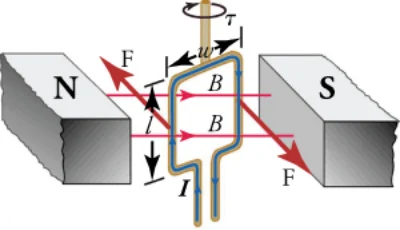
Let us examine the force on each segment of the loop in Figure 20.23 to find the torques produced about the axis of the vertical shaft—this will lead to a useful equation for the torque on the loop. We take the magnetic field to be uniform over the rectangular loop, which has width w and height as shown in the figure. First, consider the force on the top segment of the loop. To determine the direction of the force, we use the right-hand rule. The current goes from left to right into the page, and the magnetic field goes from left to right in the plane of the page. Curl your right fingers from the current vector to the magnetic field vector and your right thumb points down. Thus, the force on the top segment is downward, which produces no torque on the shaft. Repeating this analysis for the bottom segment—neglect the small gap where the lead wires go out—shows that the force on the bottom segment is upward, again producing no torque on the shaft.
図20.23の輪のそれぞれの部分にはたらく力を調べて、鉛直な軸のまわりに生じるトルクを求めよう。これが輪にはたらくトルクの役に立つ式へ導く。磁場は、図に示すように幅w、高さの長方形の輪の上で一様だとする。まず輪の上の部分にはたらく力を考える。力の向きを決めるには右手の法則を使う。電流は左から右へ紙面の奥へ向かい、磁場は紙面内で左から右へ向かう。右手の指を電流のベクトルから磁場のベクトルへ丸めると、右手の親指は下を指す。したがって上の部分にはたらく力は下向きで、軸にトルクを生まない。下の部分についても同じ分析を繰り返すと——引き出し線の出る小さな隙間は無視する——下の部分にはたらく力は上向きで、これも軸にトルクを生まないと分かる。
Consider now the left vertical segment of the loop. Again using the right-hand rule, we find that the force exerted on this segment is perpendicular to the magnetic field, as shown in Figure 20.23. This force produces a torque on the shaft. Repeating this analysis on the right vertical segment of the loop shows that the force on this segment is in the direction opposite that of the force on the left segment, thereby producing an equal torque on the shaft. The total torque on the shaft is thus twice the toque on one of the vertical segments of the loop.
次に輪の左の鉛直な部分を考えよう。また右手の法則を使うと、この部分に及ぼされる力は、図20.23に示すように磁場に垂直だと分かる。この力が軸にトルクを生む。輪の右の鉛直な部分についてこの分析を繰り返すと、この部分にはたらく力は左の部分にはたらく力と逆向きで、それによって軸に同じ大きさのトルクを生むと分かる。したがって軸にはたらく全トルクは、輪の鉛直な部分の一方にはたらくトルクの2倍である。
To find the magnitude of the torque as the wire loop spins, consider Figure 20.24, which shows a view of the wire loop from above. Recall that torque is defined as where F is the applied force, r is the distance from the pivot to where the force is applied, and θ is the angle between r and F. Notice that, as the loop spins, the current in the vertical loop segments is always perpendicular to the magnetic field. Thus, the equation gives the magnitude of the force on each vertical segment as The distance r from the shaft to where this force is applied is w/2, so the torque created by this force is
導線の輪が回るときのトルクの大きさを求めるために、導線の輪を上から見た図20.24を考えよう。トルクはと定義されたことを思い出そう。ここでFは加えられた力、rは支点から力の加わる点までの距離、θはrとFの間の角度である。輪が回るあいだ、鉛直な部分の電流はつねに磁場に垂直であることに注目しよう。したがって式から、それぞれの鉛直な部分にはたらく力の大きさはである。軸からこの力の加わる点までの距離rはw/2なので、この力が生むトルクは
Because there are two vertical segments, the total torque is twice this, or
鉛直な部分は二つあるので、全トルクはこの2倍、すなわち
If we have a multiple loop with N turns, we get N times the torque of a single loop. Using the fact that the area of the loop is the expression for the torque becomes
N回巻きの多重の輪なら、一つの輪のN倍のトルクが得られる。輪の面積がであることを使うと、トルクの式は
This is the torque on a current-carrying loop in a uniform magnetic field. This equation can be shown to be valid for a loop of any shape.
これが一様な磁場の中で電流の流れる輪にはたらくトルクである。この式はどんな形の輪でも成り立つことが示せる。
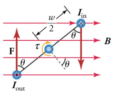
From the equation we see that the torque is zero when As the wire loop rotates, the torque increases to a maximum positive torque of when The torque then decreases back to zero as the wire loop rotates to From to the torque is negative. Thus, the torque changes sign every half turn, so the wire loop will oscillate back and forth.
式から、のときトルクは0だと分かる。導線の輪が回るにつれてトルクは増え、のとき最大の正のトルクになる。それから輪がまで回るにつれてトルクは0へ戻る。からまではトルクは負である。したがってトルクは半回転ごとに符号を変えるので、導線の輪は行ったり来たり振動することになる。
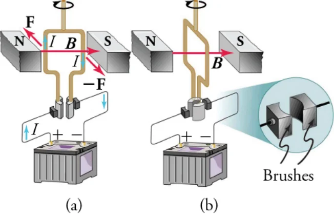
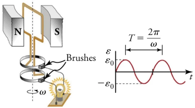
For the coil to continue rotating in the same direction, the current is reversed as the coil passes through using automatic switches called brushes, as shown in Figure 20.25.
コイルが同じ向きに回り続けるように、図20.25に示すブラシと呼ばれる自動の切り替えを使って、コイルがを通るときに電流を反転させる。
Consider now what happens if we run the motor in reverse; that is, we attach a handle to the shaft and mechanically force the coil to rotate within the magnetic field, as shown in Figure 20.26. As per the equation
ここで、電動機を逆に動かすとどうなるかを考えよう。すなわち、図20.26のように軸に取っ手をつけ、機械的にコイルを磁場の中で回す。式
—where is the angle between the vectors and in the wires of the loop experience a magnetic force because they are moving in a magnetic field. Again using the right-hand rule, where we curl our fingers from vector
——ここではベクトルとの間の角度である——により、輪の導線の中のは磁場の中を動いているので磁気の力を受ける。またベクトル
to vector , we find that charges in the top and bottom segments feel a force perpendicular to the wire, which does not cause a current. However, charges in the vertical wires experience forces parallel to the wire, causing a current to flow through the wire and through an external circuit if one is connected. A device such as this that converts mechanical energy into electrical energy is called a generator.
からベクトルへ指を丸める右手の法則を使うと、上と下の部分の電荷は導線に垂直な力を感じ、それは電流を生まないと分かる。しかし鉛直な導線の中の電荷は導線に平行な力を受け、それが導線を、そしてつながっていれば外部の回路をも流れる電流を生む。このように力学的エネルギーを電気エネルギーへ変える装置を発電機という。
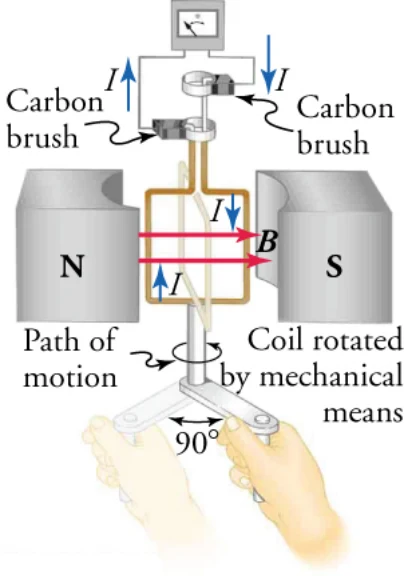
Because current is induced only in the side wires, we can find the induced emf by only considering these wires. As explained in Induced Current in a Wire, motional emf in a straight wire moving at velocity v through a magnetic field B is where the velocity is perpendicular to the magnetic field. In the generator, the velocity makes an angle with B (see Figure 20.27), so the velocity component perpendicular to B is Thus, in this case, the emf induced on each vertical wire segment is and they are in the same direction. The total emf around the loop is then
電流は側面の導線にだけ誘導されるので、この導線だけを考えれば誘導起電力を求められる。「導線に誘導される電流」で説明したとおり、磁場Bの中を速度vで動くまっすぐな導線の運動起電力はである。ここで速度は磁場に垂直である。発電機では、速度はBと角度をなす(図20.27を見よ)ので、Bに垂直な速度の成分はである。したがってこの場合、それぞれの鉛直な導線の部分に誘導される起電力はで、両者は同じ向きである。輪全体の起電力は
Although this expression is valid, it does not give the emf as a function of time. To find how the emf evolves in time, we assume that the coil is rotated at a constant angular velocity The angle is related to the angular velocity by so that
この表し方は正しいが、起電力を時間の関数として与えてはいない。起電力が時間とともにどう変わるかを求めるために、コイルが一定の角速度で回されているとする。角度は角速度とで結びついているので、
Recall that tangential velocity v is related to angular velocity by Here, , so that and
接線速度vは角速度とで結びついていたことを思い出そう。ここではなのでであり、
Noting that the area of the loop is and allowing for N wire loops, we find that
輪の面積がであることに注意し、N巻きの導線の輪を考えると、
is the emf induced in a generator coil of N turns and area A rotating at a constant angular velocity in a uniform magnetic field B. This can also be expressed as
が、一様な磁場Bの中で一定の角速度で回る、N巻きで面積Aの発電機のコイルに誘導される起電力である。これは
where
とも表せる。ここで
is the maximum (peak) emf.
が最大(尖頭)の起電力である。
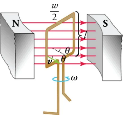
Figure 20.28 shows a generator connected to a light bulb and a graph of the emf vs. time. Note that the emf oscillates from a positive maximum of to a negative maximum of In between, the emf goes through zero, which means that zero current flows through the light bulb at these times. Thus, the light bulb actually flickers on and off at a frequency of 2f, because there are two zero crossings per period. Since alternating current such as this is used in homes around the world, why do we not notice the lights flickering on and off? In the United States, the frequency of alternating current is 60 Hz, so the lights flicker on and off at a frequency of 120 Hz. This is faster than the refresh rate of the human eye, so you don’t notice the flicker of the lights. Also, other factors prevent various different types of light bulbs from switching on and off so fast, so the light output is smoothed out a bit.
図20.28は電球につないだ発電機と、起電力対時間のグラフを示す。起電力が正の最大から負の最大まで振動することに注意しよう。その間、起電力は0を通り、そのとき電球には電流が流れない。したがって電球は実は振動数2fで点滅している。一周期に0を横切るのが2回あるからである。このような交流が世界じゅうの家庭で使われているのに、なぜ照明の点滅に気づかないのか。アメリカでは交流の振動数が60 Hzなので、照明は振動数120 Hzで点滅する。これは人の目の応答より速いので、照明の点滅に気づかない。また、他の要因のために、いろいろな型の電球はそこまで速く点いたり消えたりできず、光の出力は少しならされる。
VIRTUAL PHYSICSシミュレーションGenerator発電機
Access multimedia content (http://openstax.org/books/physics/pages/20-2-motors-generators-and-transformers) Use this simulation to discover how an electrical generator works. Control the water supply that makes a water wheel turn a magnet. This induces an emf in a nearby wire coil, which is used to light a light bulb. You can also replace the light bulb with a voltmeter, which allows you to see the polarity of the voltage, which changes from positive to negative.
マルチメディア教材はこちら(http://openstax.org/books/physics/pages/20-2-motors-generators-and-transformers) このシミュレーションで、発電機がどう働くかを調べよう。水車が磁石を回すように水の供給を制御する。これが近くの導線のコイルに起電力を誘導し、それが電球を点ける。電球を電圧計に取り替えることもでき、そうすれば電圧の極性が正から負へ変わるのが見える。
GRASP CHECK Set the number of wire loops to three, the bar-magnet strength to about 50 percent, and the loop area to 100 percent. Note the maximum voltage on the voltmeter. Assuming that one major division on the voltmeter is 5V, what is the maximum voltage when using only a single wire loop instead of three wire loops?a. 5 Vb. 15 V
理解の確認 導線の巻き数を三つ、棒磁石の強さをおよそ50パーセント、輪の面積を100パーセントにする。電圧計の最大の電圧に注目しよう。電圧計の一目盛りが5Vだとして、三巻きでなく一巻きだけを使ったときの最大の電圧はいくらか。a. 5 Vb. 15 V
c. 125 V
c. 125 V
d. 53 V
d. 53 V
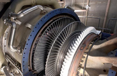
In real life, electric generators look a lot different than the figures in this section, but the principles are the same. The source of mechanical energy that turns the coil can be falling water—hydropower—steam produced by the burning of fossil fuels, or the kinetic energy of wind. Figure 20.29 shows a cutaway view of a steam turbine; steam moves over the blades connected to the shaft, which rotates the coil within the generator.
実際の発電機はこの節の図とはずいぶん違って見えるが、原理は同じである。コイルを回す力学的エネルギーの源は、落ちる水——水力——でも、化石燃料を燃やして作った蒸気でも、風の運動エネルギーでもよい。図20.29は蒸気タービンの断面図である。蒸気が軸につながった羽根の上を動き、それが発電機の中のコイルを回す。
Another very useful and common device that exploits magnetic induction is called a transformer. Transformers do what their name implies—they transform voltages from one value to another; the term voltage is used rather than emf because transformers have internal resistance. For example, many cell phones, laptops, video games, power tools, and small appliances have a transformer built into their plug-in unit that changes 120 V or 240 V AC into whatever voltage the device uses. Figure 20.30 shows two different transformers. Notice the wire coils that are visible in each device. The purpose of these coils is explained below.
磁気誘導を利用したもう一つのとても役に立つ身近な装置が変圧器である。変圧器はその名のとおり、電圧をある値から別の値へ変える。変圧器には内部抵抗があるので、起電力ではなく電圧という語を使う。たとえば多くの携帯電話・ノートパソコン・ゲーム機・電動工具・小型家電は、120 Vや240 Vの交流を装置が使う電圧へ変える変圧器を差し込み口の部分に内蔵している。図20.30は二つの違う変圧器を示す。それぞれの装置に見える導線のコイルに注目しよう。このコイルの目的は下で説明する。
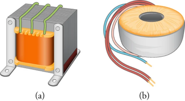
Figure 20.31 shows a laminated-coil transformer, which is based on Faraday’s law of induction and is very similar in construction to the apparatus Faraday used to demonstrate that magnetic fields can generate electric currents. The two wire coils are called the primary and secondary coils. In normal use, the input voltage is applied across the primary coil, and the secondary produces the transformed output voltage. Not only does the iron core trap the magnetic field created by the primary coil, but also its magnetization increases the field strength, which is analogous to how a dielectric increases the electric field strength in a capacitor. Since the input voltage is AC, a time-varying magnetic flux is sent through the secondary coil, inducing an AC output voltage.
図20.31は積層コイルの変圧器を示す。これはファラデーの誘導の法則にもとづき、磁場が電流を生みうることを示すのにファラデーが使った装置と作りがとてもよく似ている。二つの導線のコイルは一次コイルと二次コイルと呼ばれる。ふつうの使い方では、入力の電圧が一次コイルにかけられ、二次が変換された出力の電圧を作る。鉄心は一次コイルが作る磁場を閉じ込めるだけでなく、その磁化が場の強さを増しもする。これは誘電体がコンデンサーの電場の強さを増すのと似ている。入力の電圧は交流なので、時間とともに変わる磁束が二次コイルへ送られ、交流の出力電圧を誘導する。
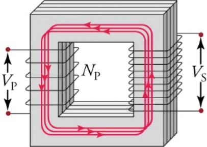
the primary coil is mostly confined to and increased by the core, which transmits it to the secondary coil. Any change in current in the primary coil induces a current in the secondary coil.
磁場は、ほとんどが鉄心に閉じ込められて強められ、鉄心がそれを二次コイルへ伝える。一次コイルの電流のどんな変化も、二次コイルに電流を誘導する。
Magnetic Rope Memory To send men to the moon, the Apollo program had to design an onboard computer system that would be robust, consume little power, and be small enough to fit onboard the spacecraft. In the 1960s, when the Apollo program was launched, entire buildings were regularly dedicated to housing computers whose computing power would be easily outstripped by today’s most basic handheld calculator.
磁気ロープメモリー 人を月へ送るために、アポロ計画は頑丈で、消費電力が小さく、宇宙船に載るほど小さい搭載コンピューターの仕組みを設計せねばならなかった。アポロ計画が始まった1960年代、建物まるごとがコンピューターの収容に充てられるのがふつうで、その計算能力は今日の最も基本的な電卓に軽く追い越されるものだった。
To address this problem, engineers at MIT and a major defense contractor turned to magnetic rope memory, which was an offshoot of a similar technology used prior to that time for creating random access memories. Unlike random access memory, magnetic rope memory was read-only memory that contained not only data but instructions as well. Thus, it was actually more than memory: It was a hard-wired computer program.
この問題に取り組むため、MITと大手の防衛企業の技術者は磁気ロープメモリーに目を向けた。これは、それ以前にランダムアクセスメモリーを作るのに使われていた似た技術から派生したものである。ランダムアクセスメモリーと違い、磁気ロープメモリーは読み出し専用のメモリーで、データだけでなく命令も収めていた。したがってそれは実のところメモリー以上のもの——配線で焼き付けられたコンピューターのプログラム——だった。
The components of magnetic rope memory were wires and iron rings—which were called cores. The iron cores served as transformers, such as that shown in the previous figure. However, instead of looping the wires multiple times around the core, individual wires passed only a single time through the cores, making these single-turn transformers. Up to 63 word wires could pass through a single core, along with a single bit wire. If a word wire passed through a given core, a voltage pulse on this wire would induce an emf in the bit wire, which would be interpreted as a one. If the word wire did not pass through the core, no emf would be induced on the bit wire, which would be interpreted as a zero.
磁気ロープメモリーの部品は導線と鉄の環で、環はコアと呼ばれた。鉄のコアは、前の図に示したような変圧器の役をした。ただし導線をコアに何度も巻きつけるのではなく、一本一本の導線がコアを一度だけ通り、これらを一巻きの変圧器にしていた。一つのコアには最大63本のワード線と、一本のビット線が通せた。ワード線があるコアを通っていれば、この線の電圧のパルスがビット線に起電力を誘導し、それは1と読まれた。ワード線がコアを通っていなければ、ビット線に起電力は誘導されず、それは0と読まれた。
Engineers would create programs that would be hard wired into these magnetic rope memories. The wiring process could take as long as a month to complete as workers painstakingly threaded wires through some cores and around others. If any mistakes were made either in the programming or the wiring, debugging would be extraordinarily difficult, if not impossible.
技術者は、この磁気ロープメモリーに配線で焼き付けるプログラムを作った。作業員があるコアには導線を通し、他のコアには通さないという骨の折れる作業をしたので、配線には一か月もかかることがあった。プログラムか配線に誤りがあれば、不具合を見つけるのは不可能ではないにしてもきわめて難しかった。
These modules did their job quite well. They are credited with correcting an astronaut mistake in the lunar landing procedure, thereby allowing Apollo 11 to land on the moon. It is doubtful that Michael Faraday ever imagined such an application for magnetic induction when he discovered it.
この装置はきわめてよく働いた。月着陸の手順での宇宙飛行士の誤りを正し、それによってアポロ11号が月に着陸できたとされている。マイケル・ファラデーが磁気誘導を見つけたとき、そんな応用を想像したとは思えない。
If the bit wire were looped twice around each core, how would the voltage induced in the bit wire be affected?a. If number of loops around the wire is doubled, the emf is halved.b. If number of loops around the wire is doubled, the emf is not affected.
ビット線がそれぞれのコアに二度巻きつけられていたら、ビット線に誘導される電圧はどうなるか。a. 巻き数が2倍になれば起電力は半分になる。b. 巻き数が2倍になっても起電力は変わらない。
c. If number of loops around the wire is doubled, the emf is also doubled.d. If number of loops around the wire is doubled, the emf is four times the initial value.
c. 巻き数が2倍になれば起電力も2倍になる。d. 巻き数が2倍になれば起電力は初めの値の4倍になる。
For the transformer shown in Figure 20.31, the output voltage from the secondary coil depends almost entirely on the input voltage across the primary coil and the number of loops in the primary and secondary coils.Faraday’s law of induction for the secondary coil gives its induced output voltage to be
図20.31の変圧器では、二次コイルからの出力電圧は、ほとんどまったく一次コイルにかかる入力電圧と、一次・二次コイルの巻き数だけで決まる。二次コイルについてのファラデーの誘導の法則は、その誘導される出力電圧を
where is the number of loops in the secondary coil and is the rate of change of magnetic flux. The output voltage equals the induced emf provided coil resistance is small—a reasonable assumption for transformers. The cross-sectional area of the coils is the same on each side, as is the magnetic field strength, and so is the same on each side. The input primary voltage is also related to changing flux by
ここでは二次コイルの巻き数、は磁束の変化の速さである。コイルの抵抗が小さければ——変圧器では妥当な仮定である——出力電圧は誘導起電力に等しい。コイルの断面積は両側で同じであり、磁場の強さも同じなので、は両側で同じである。入力の一次電圧も、変わる磁束と
Taking the ratio of these last two equations yields the useful relationship
最後の二つの式の比をとると、次の役に立つ関係が得られる。
This is known as the transformer equation. It simply states that the ratio of the secondary voltage to the primary voltage in a transformer equals the ratio of the number of loops in secondary coil to the number of loops in the primary coil.
これは変圧器の式として知られる。それは単に、変圧器の二次電圧と一次電圧の比が、二次コイルの巻き数と一次コイルの巻き数の比に等しいと述べている。
Transmission of Electrical Power電力の送電
Transformers are widely used in the electric power industry to increase voltages—called step-up transformers—before long-distance transmission via high-voltage wires. They are also used to decrease voltages—called step-down transformers—to deliver power to homes and businesses. The overwhelming majority of electric power is generated by using magnetic induction, whereby a wire coil or copper disk is rotated in a magnetic field. The primary energy required to rotate the coils or disk can be provided by a variety of means. Hydroelectric power plants use the kinetic energy of water to drive electric generators. Coal or nuclear power plants create steam to drive steam turbines that turn the coils. Other sources of primary energy include wind, tides, or waves on water.
変圧器は電力産業で、高電圧の電線による長距離の送電の前に電圧を上げるのに広く使われる——これを昇圧変圧器という。また家庭や事業所へ電力を届けるために電圧を下げるのにも使われる——これを降圧変圧器という。電力の圧倒的大部分は磁気誘導によって作られる。導線のコイルや銅の円板を磁場の中で回すのである。コイルや円板を回すのに要る一次のエネルギーは、さまざまな手段で与えられる。水力発電所は水の運動エネルギーで発電機を動かす。石炭火力や原子力の発電所は蒸気を作り、それが蒸気タービンを動かしてコイルを回す。他の一次エネルギーの源には、風、潮汐、水の波がある。
Once power is generated, it must be transmitted to the consumer, which often means transmitting power over hundreds of kilometers. To do this, the voltage of the power plant is increased by a step-up transformer, that is stepped up, and the current decreases proportionally because
電力ができたら、それを消費者へ送らねばならない。それはしばしば何百キロメートルも電力を送ることを意味する。そのために発電所の電圧は昇圧変圧器で上げられ、それに比例して電流が減る。
The lower current in the transmission wires reduces the Joule losses, which is heating of the wire due to a current flow. This heating is caused by the small, but nonzero, resistance of the transmission wires. The power lost to the environment through this heat is
送電線の電流が小さくなれば、ジュール損——電流が流れることによる導線の発熱——が減る。この発熱は、送電線の小さいが0でない抵抗によって起こる。この熱を通して環境へ失われる電力は
which is proportional to the current squared in the transmission wire. This is why the transmitted current must be as small as possible and, consequently, the voltage must be large to transmit the power
であり、送電線の電流の2乗に比例する。だから送る電流はできるだけ小さくなければならず、したがって次の電力を送るには電圧が大きくなければならない。
Voltages ranging from 120 to 700 kV are used for transmitting power over long distances. The voltage is stepped up at the exit of the power station by a step-up transformer, as shown in Figure 20.32.
長距離の送電には120から700 kVの電圧が使われる。図20.32に示すように、電圧は発電所の出口で昇圧変圧器によって上げられる。
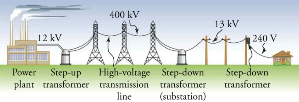
Once the power has arrived at a population or industrial center, the voltage is stepped down at a substation to between 5 and 30 kV. Finally, at individual homes or businesses, the power is stepped down again to 120, 240, or 480 V. Each step-up and step-down transformation is done with a transformer designed based on Faradays law of induction. We’ve come a long way since Queen Elizabeth asked Faraday what possible use could be made of electricity.
電力が人口の集まる場所や工業の中心に届くと、電圧は変電所で5から30 kVへ下げられる。最後に個々の家庭や事業所で、電力はさらに120、240、480 Vへ下げられる。この昇圧と降圧の変換はどれも、ファラデーの誘導の法則にもとづいて設計された変圧器で行われる。エリザベス女王がファラデーに電気は何の役に立つのかと尋ねてから、ずいぶん遠くまで来たものである。
Check Your Understanding理解の確認
7What is an electric motor?a. An electric motor transforms electrical energy into mechanical energy.b. An electric motor transforms mechanical energy into electrical energy.c. An electric motor transforms chemical energy into mechanical energy.d. An electric motor transforms mechanical energy into chemical energy.
7電動機とは何か。a. 電動機は電気エネルギーを力学的エネルギーへ変える。b. 電動機は力学的エネルギーを電気エネルギーへ変える。c. 電動機は化学エネルギーを力学的エネルギーへ変える。d. 電動機は力学的エネルギーを化学エネルギーへ変える。
8What happens to the torque provided by an electric motor if you double the number of coils in the motor?a. The torque would be doubled.b. The torque would be halved.
8電動機のコイルの数を2倍にすると、電動機が与えるトルクはどうなるか。a. トルクは2倍になる。b. トルクは半分になる。
c. The torque would be quadrupled.d. The torque would be tripled.
c. トルクは4倍になる。d. トルクは3倍になる。
9What is a step-up transformer?a. A step-up transformer decreases the current to transmit power over short distances with minimum loss.b. A step-up transformer increases the current to transmit power over short distances with minimum loss.c. A step-up transformer increases voltage to transmit power over long distances with minimum loss.d. A step-up transformer decreases voltage to transmit power over short distances with minimum loss.
9昇圧変圧器とは何か。a. 昇圧変圧器は、短い距離を最小の損失で送電するために電流を下げる。b. 昇圧変圧器は、短い距離を最小の損失で送電するために電流を上げる。c. 昇圧変圧器は、長い距離を最小の損失で送電するために電圧を上げる。d. 昇圧変圧器は、短い距離を最小の損失で送電するために電圧を下げる。
10What should be the ratio of the number of output coils to the number of input coil in a step-up transformer to increase the voltage fivefold?
10電圧を5倍にする昇圧変圧器では、出力側のコイルの巻き数と入力側のコイルの巻き数の比はいくらであるべきか。
a. The ratio is five times.b. The ratio is 10 times.c. The ratio is 15 times.d. The ratio is 20 times.
a. 比は5倍。b. 比は10倍。c. 比は15倍。d. 比は20倍。