第9章ソフトウェア工学
Software Process Framework Activitiesソフトウェアプロセスの枠組み上の活動
A good portion of a software engineer’s role is spent within the various framework activities of an SDLC. As such, it is critical for a software engineer to understand the key elements of each of the various framework activities that are used to create software solutions. As you may recall, these framework activities or phases were introduced earlier as inception, elaboration, construction, and deployment. These activities provide a structured approach to creating software solutions. By understanding these framework activities and the tasks involved in each phase, you will be well equipped to contribute effectively to the software engineering process.
英語のヒント
エンジニアの仕事の大きな部分は、SDLCのさまざまな基本的活動のなかで行われる。そのため、ソフトウェアによる仕組みを作る際に用いる各活動の重要な要素を理解することが不可欠である。先ほど紹介したとおり、これらの活動、すなわちフェーズには、立ち上げ、推敲、構築、配備がある。これらは、仕組みを作るための体系的なアプローチを示す。各活動と各フェーズ内のタスクを理解すれば、ソフトウェア工学の工程へ効果的に貢献するための、確かな備えとなる。
Inception Framework Activity立ち上げの活動
A core precondition to the creation of a solution is to know what must be developed. It is easy to say you want to add automation features to an automobile, but what does that really mean? What are the specific expectations and how do they relate to the solution that needs to be created? In order to create a solution, you have to understand what the solution is expected to do.
英語のヒント
仕組みを作るうえでの基本的な前提は、何を開発しなければならないかを知ることである。自動車に自動化の機能を加えたい、と言うのは簡単だが、実際には何を意味するのだろう。具体的な期待は何であり、作るべき仕組みとどう関係するのだろう。作成に着手するには、その仕組みに何をしてほしいのかを理解しなければならない。
The inception phase of a project focuses on the gathering and refinement (i.e., definition) as well as the management of functional and nonfunctional requirements, which is also known as requirements engineering. In essence, the inception phase covers the planning activity that lays a project foundation. Here, you will define the project goals, identify the overall scope of the software (what features it will have), and conduct feasibility studies to assess if the project is realistic and achievable. As an example, imagine you are building a recipe app. In this phase, you would decide what features the app should have (like searching for recipes or creating grocery lists) and estimate the time and resources needed to develop it.
英語のヒント
プロジェクトの立ち上げのフェーズでは、機能要件と非機能要件の収集・詳細化、つまり定義と、それらの管理を重視する。これは要求工学とも呼ばれる。要するに、立ち上げはプロジェクトの土台を築く計画の活動である。目標を定義し、ソフトウェア全体の範囲、すなわちどの機能を備えるかを明らかにし、プロジェクトが現実的で達成可能かを評価する実現可能性調査を行う。たとえば、料理のレシピを扱うアプリを作るとしよう。このフェーズでは、レシピ検索や買い物リストの作成など、アプリにどの機能を備えるべきかを決め、開発に必要な時間と資源を見積もる。
Defining requirements must involve stakeholders because they know what the software system should do better than others. Requirements definition involves obtaining the requirements from stakeholders and analyzing/decomposing strategic requirements until you can identify tactical actionable requirements. These will form a foundation for the creation of the analysis model. This definition process is done with either a use case, which describes how the software system is expected to be employed by users to accomplish a goal or requirement, or as a user story, which is a generic explanation aimed at the user to tell them how a software features works. Requirements management relates to handling changes in requirements and identifying the effect of such changes on the existing set of engineered requirements.
英語のヒント
要求の定義には、利害関係者が参加しなければならない。ソフトウェアシステムが何をすべきかを、ほかの人々よりよく知っているからである。利害関係者から要求を収集し、戦略的な要求を分析・分解して、具体的な行動につなげられる戦術的な要求まで明らかにする。これが分析モデルの土台となる。定義には、利用者が目標や要求を達成するためにシステムをどう使うかを記述するユースケース、または、利用者に機能の働き方を伝える一般的な説明であるユーザーストーリーを用いる。要求管理は、要求の変化を扱い、その変更が、既に整理された一連の要求へどのような影響を及ぼすかを明らかにすることである。
Although the software engineering actions and task sets that relate to the drawing forth of requirements may appear straightforward at first sight, it is in fact one of the trickiest parts of the SDLC. This is due to a gap that always exists between the way stakeholders and business analysts understand the requirements as compared to the way they are perceived by software engineers. This is especially true when you develop a software solution for a particular expert group that use their own terminology; often those who perform a process take some of the actions they do for granted.
英語のヒント
要求を引き出すアクションやタスクの集合は、一見単純に見えるかもしれない。しかし、実際にはSDLCのなかでも特に難しい部分の一つである。利害関係者や業務分析者による要求の理解と、ソフトウェアエンジニアの受け止め方との間に、常に隔たりがあるためだ。独自の用語を使う特定の専門家集団に向けて開発する場合には、とりわけこの問題が大きい。仕事を実際に行う人は、自分たちの作業の一部を当然のことと受け止め、説明しないことがよくある。
The inception phase results in a specification of the system to be developed. This specification is generally incomplete and/or anomalous and is typically refined as part of subsequent process phases (or iterations of such). As a result, there is a blurred distinction between requirements specification, design, and construction.
英語のヒント
立ち上げのフェーズでは、開発するシステムの仕様が成果として得られる。この仕様は一般に不完全だったり不整合があったりするため、後続のフェーズ、あるいはその反復のなかで詳細化する。したがって、要求仕様、設計、構築の間の区別は、明確なものではない。
The actual software engineering actions and task sets that are used as part of the inception phase involve gaining an understanding of the solution context and collaboratively gathering, decomposing, and tracking requirements to help elaborate a preliminary analysis model. Once the preliminary analysis model is created, requirements can then be negotiated and validated with the stakeholders via an in-person Joint Application Design (JAD) session, an approach that involves assembling stakeholders and developers, or through the use of collaborative requirements modeling tools that enable scenario-based modeling. After this, detailed requirements modeling takes place.
英語のヒント
立ち上げで実際に行うアクションやタスクには、仕組みを取り巻く状況を理解し、関係者と協力して要求を収集・分解・追跡し、暫定的な分析モデルを作ることが含まれる。そのモデルができたら、利害関係者と開発者が対面で集まる共同アプリケーション設計(JAD)の会合で、要求を交渉し検証することができる。また、シナリオに基づくモデリングを可能にする共同作業用の要求モデリングツールを使う方法もある。その後、要求の詳細なモデリングを行う。
Agile requirements definition attempts to accelerate the gathering and analysis/decomposition of requirements. The guidelines it uses to speed this process include:
アジャイル型の要求定義では、要求の収集と分析・分解を速めようとする。この工程を加速させる指針には、次のものがある。
1. Use simple models such as fast sketches and user stories to allow all stakeholders to participate.
1. 手早いスケッチやユーザーストーリーなどの単純なモデルを使い、すべての利害関係者が参加できるようにする。
2. Adopt user, client, or expert group terminology and avoid technical jargon whenever possible.
2. 利用者、顧客、専門家集団の用語を取り入れ、可能な限り技術的な専門用語を避ける。
3. Get the big picture of the project done before getting bogged down in details.
英語のヒント
3. 細部に足を取られる前に、プロジェクトの全体像をまとめる。
4. Refine requirements throughout the project and allow additions and revisions to occur at any time.
4. プロジェクト全体を通して要求を練り上げ、いつでも追加や改訂ができるようにする。
5. Implement the most important user stories first and only once its requirements are fully specified.
5. 最も重要なユーザーストーリーから実装する。ただし、その要求が完全に特定できてから着手する。
6. Make the current set of requirements available to all stakeholders so everyone can participate in selecting the features to add during the next development cycle.
6. 現在の一連の要求をすべての利害関係者が閲覧できるようにし、次の開発サイクルで追加する機能の選択に、全員が参加できるようにする。
Various tools may be leveraged to support the software engineering actions and task sets that pertain to the inception phase (e.g., ReqView3 ).
英語のヒント
立ち上げに関わるアクションやタスクの集合を支えるため、ReqView3などの各種ツールを利用できる。
Requirements Modeling
要求モデリング
The software engineering action that is part of the inception phase and focuses on the analysis/decomposition of software requirements is called requirements modeling. The goal of this action is to answer the question “What will the system do?” The focus is purely conceptual, and implementation details are not considered. The main purpose of this analysis is to understand the requirements at a level that makes it possible to design and implement a software system that meets the customer’s needs.
英語のヒント
立ち上げのフェーズの一部として、ソフトウェア要求の分析・分解に焦点を当てるソフトウェア工学のアクションを、要求モデリングという。この活動の目標は、「システムは何をするのか」という問いに答えることである。概念的な内容だけに焦点を当て、実装の詳細は考慮しない。分析の主な目的は、顧客のニーズを満たすシステムを設計・実装できる水準まで、要求を理解することにある。
3 https://www.reqview.com/
3 https://www.reqview.com/
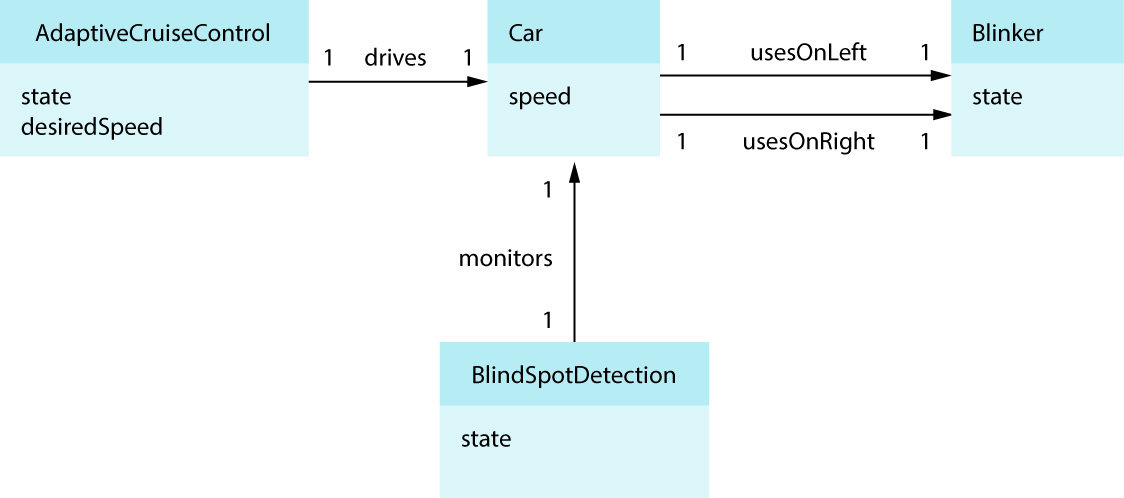
As part of requirements modeling, as in business use case modeling, you typically create a domain model that captures the major concepts of the problem domain and associations between them. For example, in the domain of driving assists for an automotive solution, there could be conceptual/analysis classes such as AdaptiveCruiseControl, Car, BlindSpotDetection, and Blinker and class attributes assigned to classes as follows:
英語のヒント
要求モデリングでは、業務のユースケースモデリングと同様に、問題領域の主要な概念と、それらの間の関連を表すドメインモデルを作るのが一般的である。たとえば、自動車の運転支援という領域には、AdaptiveCruiseControl、Car、BlindSpotDetection、Blinkerなどの概念上のクラス、すなわち分析クラスが考えられる。各クラスには、次のように属性を割り当てられる。
• AdaptiveCruiseControl has attributes state (on/off) and desiredSpeed (the requested speed).
• AdaptiveCruiseControlには、state(オン/オフ)とdesiredSpeed(指定された速度)という属性がある。
• Car has attribute speed (the current speed).
• Carには、speed(現在の速度)という属性がある。
• BlindSpotDetection has attribute state (on/off).
• BlindSpotDetectionには、state(オン/オフ)という属性がある。
• Blinker has attribute state (on/off).
• Blinkerには、state(オン/オフ)という属性がある。
Figure 9.5 illustrates a class diagram of a partial domain model. This diagram is specified using Unified Modeling Language (UML). UML is often used for modeling in projects as its visual representations provide clear, compact means of communicating among the developers. In UML class diagrams such as this, the numbers at associations are multiplicities, and the arrows specify the direction in which you are expected to read the association. For example, BlindSpotDetection monitors Car.
英語のヒント
図9.5は、ドメインモデルの一部分をクラス図で示している。この図は統一モデリング言語(UML)で記述されている。UMLの視覚表現は、開発者同士が明確かつ簡潔に意思疎通する手段となるため、プロジェクトのモデリングでよく使われる。このようなUMLクラス図では、関連に付いた数値は多重度を表し、矢印はその関連を読む向きを示す。たとえば、「BlindSpotDetectionがCarを監視する」と読む。
attribution: Copyright Rice University, OpenStax, under CC BY 4.0 license · CC BY 4.0 · Source出典
Figure 9.5 A UML class diagram, in this case of a partial domain model, is used as a communication tool among developers. (attribution: Copyright Rice University, OpenStax, under CC BY 4.0 license)
図9.5 UMLクラス図は、開発者同士の意思疎通の道具として使われる。ここではドメインモデルの一部分を示している。(帰属:Rice University、OpenStax著作権、CC BY 4.0ライセンス。)
Associations are links that deserve to be stored in the system. For example, an association between AdaptiveCruiseControl and Car is required because when Adaptive Cruise Control is active, conceptual class AdaptiveCruiseControl needs access to the car. The numbers at associations are multiplicities, and they say that there is exactly one Car associated with each AdaptiveCruiseControl and that there is exactly one AdaptiveCruiseControl associated with each Car. Associations can have names, which facilitate reading and understanding the analysis model.
英語のヒント
関連は、システムに記録しておく意味のある結びつきである。たとえば、アダプティブクルーズコントロールが作動中は、概念クラスAdaptiveCruiseControlから自動車へアクセスする必要があるため、AdaptiveCruiseControlとCarの間の関連が必要になる。関連に付いた数値は多重度を表す。この場合、各AdaptiveCruiseControlにはちょうど一つのCarが関連づけられ、各Carにはちょうど一つのAdaptiveCruiseControlが関連づけられることを示している。関連に名前を付ければ、分析モデルを読み、理解しやすくなる。
The UML notation may be applied to provide different perspectives as follows:
UMLの記法は、次のような異なる視点を表すのに使える。
• Conceptual perspective: The diagrams describe real-world concepts or things.
• 概念の視点:現実世界の概念や物を図で表す。
• Specification (software) perspective: The diagrams describe software components.
• 仕様の視点(ソフトウェア):ソフトウェアの構成要素を図で表す。
• Implementation (software) perspective: The diagrams describe software components in a particular technology, such as Java or .NET.
• 実装の視点(ソフトウェア):Javaや.NETなど、特定の技術を用いたソフトウェアの構成要素を図で表す。
We typically use all perspectives throughout the software development life cycle: conceptual perspective to capture requirements, specification perspective to describe the design, and implementation perspective to clarify implementation details.
開発ライフサイクル全体では、通常これらのすべての視点を使う。要求を捉えるときは概念の視点、設計を記述するときは仕様の視点、実装の詳細を明確にするときは実装の視点を用いる。
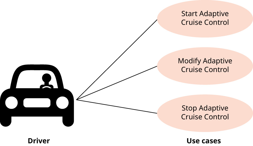
When doing requirements analysis, you can create specific outputs/work products (also referred to as artifacts), such as use cases, scenarios, and the domain model. Use cases can be captured in plain text or via a UML Use Case diagram. A Use Case diagram consists of an actor, which represents users of the system, and the use cases that this user is expected to use. In Figure 9.6, the actor is a driver who might be seeking to turn on cruise control. Each use case is then described in detail using one or more scenarios. A scenario is a specific instance of operational flow within a use case that is focused on understanding a specific action. Scenarios are written either in a plain text or as a sequence of steps that describe a specific scenario instance within a use case (i.e., main scenario describing the most productive set of steps versus alternative scenarios that capture unexpected behavior).
英語のヒント
要求分析では、ユースケース、シナリオ、ドメインモデルなど、具体的な出力・作業成果物を作成できる。これらはアーティファクトとも呼ばれる。ユースケースは、通常の文章やUMLユースケース図で記録できる。ユースケース図は、システムの利用者を表すアクターと、その利用者が使うと想定されるユースケースで構成される。図9.6では、クルーズコントロールをオンにしようとする運転者がアクターである。各ユースケースは、一つ以上のシナリオで詳しく記述する。シナリオとは、特定の行動を理解することに焦点を当てた、ユースケース内の操作の流れの具体例である。通常の文章、または一連の手順で記す。最も生産的な一連の手順を記述する主シナリオに対して、代替シナリオでは想定外の振る舞いを捉える。
attribution: Copyright Rice University, OpenStax, under CC BY 4.0 license · CC BY 4.0 · Source出典
Figure 9.6 In this UML use case diagram illustrating an actor called “Driver,” the three use cases might be further grouped together and categorized as Car Control system. (attribution: Copyright Rice University, OpenStax, under CC BY 4.0 license)
図9.6 「Driver」というアクターを示したUMLユースケース図。三つのユースケースをさらにまとめ、自動車制御システムとして分類することもできる。(帰属:Rice University、OpenStax著作権、CC BY 4.0ライセンス。)
As part of requirements modeling, UML diagrams are drawn whenever they bring value to help provide a conceptual perspective of what the solution is meant to accomplish. They are generally not required to be complete or perfect. The use of UML in this manner is typically referred to as “UML as sketch,” and it involves informal and incomplete diagrams. Instead of drawing UML diagrams, it is possible to specify them via scripts to automate the creation of diagrams, which can save valuable time. As mentioned, the main goal of requirements analysis/decomposition in the inception phase is to understand the problem while the main goal of the elaboration phase, which comes next and involves software design, is to clarify what we are to implement.
英語のヒント
要求モデリングでは、仕組みが何を実現すべきかを概念的に示すのに役立つとき、UML図を描く。一般に、完全で完璧な図である必要はない。この使い方は「スケッチとしてのUML」と呼ばれ、非形式的で未完成の図を用いる。図を手で描く代わりにスクリプトで指定し、その生成を自動化すれば、貴重な時間を節約できる。既に述べたように、立ち上げにおける要求の分析・分解の主目的は、問題を理解することである。一方、その次に行う、ソフトウェアの設計を含む推敲のフェーズでは、何を実装するのかを明確にすることが主目的となる。